Getting started with XC3/XD3/XS3
This getting started guide describes how to initially connect the device, open the web interface and setup device user and network settings.
The Hardware
XC3
Back
| Port | Type | Comment |
|---|---|---|
| IPx 1 P | RJ45 LAN / Ethernet interface | Factory-Equipped IPx Interface, network communication interface of the core |
| IPx 1 S | RJ45 LAN / Ethernet interface | Factory-Equipped IPx Interface, network communication interface of the core |
| IPx 2 P | RJ45 LAN / Ethernet interface | Optional IPx audio over IP Interface |
| IPx 2 S | RJ45 LAN / Ethernet interface | Optional IPx audio over IP Interface |
| GA1 - GA4 | Gigabit Audio / MADI | Function depending on equipped optional SFP module |
| APC 1 - APC 12 | RJ45 DHD APC port | Connect DHD modules like Surfaces or I/O Modules. No switched ethernet interface, only for direct point to point connection. |
| Sync In/Out | HD BNC multi format | Sync sources can be: BNC Wordclock (Rising Edge) BNC Wordclock (Falling Edge) BNC AES EBU BNC Video (NTSC/PAL) |
| sAPC | USB-C proprietary | Reserved for future use. Not USB-C compatible. |
| 48V 1 - 48V 2 | Power supply | Redundant power supply inputs |
| LED | Function |
|---|---|
| DC | Indicates at least working PSU connected |
| Button | Function |
|---|---|
| FCT | Press and hold min. 5 seconds: Reset Admin User Password Press and hold min. 20 seconds: Reset Admin User Password, Network & Security Settings |
Front
| LED | Function | Color | Speed | Meaning |
|---|---|---|---|---|
| State 1 | Controller status | Green | permanently on | Controller running |
| State 2 | Internal DSPx module status | Green | Fast blinking | DSPx module running |
| Green/yellow | Fast/slow blinking | Updating | ||
| Power | Gives information about PSU state | Green | permanently on | PSU ok |
| Yellow | permanently on | PSU failure (1 remaining), check system app for details. Only applies if more than 1 PSU configured in Toolbox |
||
| Off | Off | No power | ||
| Sync | Gives information about current sync source | Green | permanently on | Sync 1 synced |
| Green/Yellow | Alternating | Sync 1 synced, sync 2 not ready | ||
| Yellow | permanently on | Sync 2 synced, sync 1 not available | ||
| Off | Off | Internal sync, sync 1 and 2 not available | ||
| IPx 1 | IPx 1 module and Core Firmware status | Green | Fast blinking | IPx 1 module and core firmware running |
| Green/yellow | Fast/slow blinking | Updating | ||
| IPx 2 | IPx 2 module and Firmware status (optional, only if equipped) | Green | Fast blinking | IPx 2 module running |
| Green/yellow | Fast/slow blinking | Updating | ||
| CPU | CPU running indication | Green | Slow blinking | CPU running |
| DSPx | Additional DSPx module status (optional, only if equipped) | Green | Fast blinking | Additional DSPx module running |
| Green | Slow blinking | Additional DSPx module not configured | ||
| Off | Off | Additional DSPx module not installed |
Note
For more detailed information on LED behaviour, see Meaning of LEDs
| Button | Function |
|---|---|
| Reset | Hardware Reset Button. See Reset Behaviour. |
XD3
Back
| Port | Type | Comment |
|---|---|---|
| ETH1 / ETH2 | RJ45 LAN / Ethernet interface, Bond interface | Bond Ethernet interface, network communication interface of the core |
| ETH3 | RJ45 LAN / Ethernet interface | Network communication interface of the core |
| ETH4 | RJ45 LAN / Ethernet interface | Network communication interface of the core |
| APC 1 - APC 4 | RJ45 DHD APC port | Connect DHD modules like Surfaces or I/O Modules. No switched ethernet interface, only for direct point to point connection. |
| S/R | RS232 Serial interface | For serial protocol connection with a PC or interconnection to second redundancy core |
| IPx 1 P | RJ45 LAN / Ethernet interface | Optional IPx audio over IP Interface |
| IPx 1 S | RJ45 LAN / Ethernet interface | Optional IPx audio over IP Interface |
| IPx 2 P | RJ45 LAN / Ethernet interface | Optional IPx audio over IP Interface |
| IPx 2 S | RJ45 LAN / Ethernet interface | Optional IPx audio over IP Interface |
| GA1 - GA4 | Gigabit Audio / MADI | Function depending on equipped optional SFP module |
| Sync In/Out | HD BNC multi format | Sync sources can be: BNC Wordclock (Rising Edge) BNC Wordclock (Falling Edge) BNC AES EBU BNC Video (NTSC/PAL) |
| sAPC | USB-C proprietary | Reserved for future use. Not USB-C compatible. |
| 48V 1 - 48V 2 | Power supply | Redundant power supply input |
| LED | Function |
|---|---|
| DC | Indicates at least working PSU connected |
| Button | Function |
|---|---|
| FCT | Press and hold min. 5 seconds: Reset Admin User Password Press and hold min. 20 seconds: Reset Admin User Password, Network & Security Settings |
Front
| Port | Type | Comment |
|---|---|---|
| USB | USB-C | For service and recovery purposes |
| LED | Function | Color | Speed | Meaning |
|---|---|---|---|---|
| State 1 | Controller status | Green | permanently on | Controller running |
| State 2 | Internal DSPx module status | Green | Fast blinking | DSPx module running |
| Power | Gives information about PSU state | Green | permanently on | PSU ok |
| Yellow | permanently on | PSU failure (1 remaining), check system app for details. Only applies if more than 1 PSU configured in Toolbox |
||
| Off | Off | No power | ||
| Sync | Gives information about current sync source | Green | permanently on | Sync 1 synced |
| Green/Yellow | Alternating | Sync 1 synced, sync 2 not ready | ||
| Yellow | permanently on | Sync 2 synced, sync 1 not available | ||
| Off | Off | Internal sync, sync 1 and 2 not available | ||
| IPx 1 | IPx 1 module and Firmware status (optional, only if equipped) | Green | Fast blinking | IPx 1 module running |
| IPx 2 | IPx 2 module and Firmware status (optional, only if equipped) | Green | Fast blinking | IPx 2 module running |
| CPU | CPU running indication | Green | Slow blinking | CPU running |
| RED | Redundancy status information | Green | Slow blinking | Redundancy enabled, unit is A and Main |
| Green | permanently on | Redundancy enabled, unit is B and Backup | ||
| Yellow | Slow blinking | Redundancy enabled, unit is B and Main | ||
| Yellow | permanently on | Redundancy enabled, unit is A and Backup | ||
| Green/Yellow | Alternating | Slave not ready | ||
| Off | Off | Redundancy disabled |
Note
For more detailed information on LED behaviour, see Meaning of LEDs
| Button | Function |
|---|---|
| Reset | Hardware Reset Button. See Reset Behaviour. |
XD3 optional router part: Back
| GA5-GA24 | Gigabit Audio / MADI | Function depending on equipped optional SFP module. Port usability also depending on number of equipped optional DSPx modules |
XD3 optional router part: Front
| LED | Function | Color | Speed | Meaning |
|---|---|---|---|---|
| State 1 | Controller status | Green | permanently on | Controller running |
| State 2 | Internal router and integrated DSPx module status | Green | Fast blinking | Router and DSPx module running |
| DSPx 1-DSPx 4 | Additional DSPx module status (optional, only if equipped) | Green | Fast blinking | Additional DSPx module running |
| Green | Slow blinking | Additional DSPx module not configured | ||
| Off | Off | Additional DSPx module not installed |
Note
For more detailed information on LED behaviour, see Meaning of LEDs
XS3
Back
| Port | Type | Comment |
|---|---|---|
| IPx 1 P | RJ45 LAN / Ethernet interface | Factory-Equipped IPx Interface, network communication interface of the core |
| IPx 1 S | RJ45 LAN / Ethernet interface | Factory-Equipped IPx Interface, network communication interface of the core |
| IPx 2 P | RJ45 LAN / Ethernet interface | Optional IPx audio over IP Interface |
| IPx 2 S | RJ45 LAN / Ethernet interface | Optional IPx audio over IP Interface |
| USB | USB Audio | 16×16 ch USB audio interface for MAC/PC. See Getting started with XS3 USB Audio 16x16 Interface for detailed instructions. |
| MADI | MADI | |
| sAPC | USB-C proprietary | Reserved for future use. Not USB-C compatible. |
| Dante 4×4 | Dante Audio Network | Independent Dante audio network interface. |
| APC 1 - APC 8 | RJ45 DHD APC port | Connect DHD modules like Surfaces or I/O Modules. No switched ethernet interface, only for direct point to point connection. Mind the different order of APC ports! |
| Sync In/Out | HD BNC multi format | Optional module - Sync sources can be: BNC Wordclock (Rising Edge) BNC Wordclock (Falling Edge) BNC AES EBU BNC Video (NTSC/PAL) |
| 48V 1 - 48V 2 | Power supply | Redundant power supply inputs |
| LED | Function |
|---|---|
| FL | Indicates at least working PSU connected |
| Button | Function |
|---|---|
| FCT | Press and hold min. 5 seconds: Reset Admin User Password Press and hold min. 20 seconds: Reset Admin User Password, Network & Security Settings |
Front
| LED | Function | Color | Speed | Meaning |
|---|---|---|---|---|
| State 1 | Controller status | Green | permanently on | Controller running |
| State 2 | Internal DSP module status | Green | Fast blinking | DSP module running |
| Green/yellow | Fast/slow blinking | Updating | ||
| Power | Gives information about PSU state | Green | permanently on | PSU ok |
| Yellow | permanently on | PSU failure (1 remaining), check system app for details. Only applies if more than 1 PSU configured in Toolbox |
||
| Off | Off | No power | ||
| Sync | Gives information about current sync source | Green | permanently on | Sync 1 synced |
| Green/Yellow | Alternating | Sync 1 synced, sync 2 not ready | ||
| Yellow | permanently on | Sync 2 synced, sync 1 not available | ||
| Off | Off | Internal sync, sync 1 and 2 not available | ||
| IPx 1 | IPx 1 module and Core Firmware status | Green | Fast blinking | IPx 1 module and core firmware running |
| Green/yellow | Fast/slow blinking | Updating | ||
| IPx 2 | IPx 2 module and Firmware status (optional, only if equipped) | Green | Fast blinking | IPx 2 module running |
| Green/yellow | Fast/slow blinking | Updating | ||
| CPU | CPU running indication | Green | Slow blinking | CPU running |
| USB | USB Data Status | Green | permanently on | USB data connection is currently active |
| Off | USB data connection is currently inactive or USB not connected | |||
| Dante 4×4 | Dante 4×4 Status | Green | permanently on | Dante 4×4 is ok and synced to the current PTP leader clock |
| Green | slow blinking | Dante 4×4 is ok and - is the current PTP leader clock - network port is not connected - Dante Controller's Identify device function was activated |
||
| Yellow | slow blinking | Dante 4×4 is in failsafe mode - check Dante Controller |
Note
For more detailed information on LED behaviour, see Meaning of LEDs
| Button | Function |
|---|---|
| Reset | Hardware Reset Button. See Reset Behaviour. |
Power Up the Device
Connect the device to the power supply using the power supply unit(s). The device has no power switch and should begin booting up completely. Wait until “State 2”-LED starts flashing fast. The device is now booted.
Connect to the Device
Since Version 10.1 and higher the default network settings have basically changed.
Port IPx1 P on XS3 and XC3 Cores and ETH1/ETH2 on XD3 Cores is always set to DHCP. If no DHCP Server can be found the Core will use DHCP / Zeroconf to find itself an IP Address in the range of 169.254.0.0/16.
Port IPx1 S (ETH4 on XD3) is by default set to a fixed address in the 10.0.0.0/8 range, using our well-known MAC addressing scheme. But instead of using the 10.5.*.* address a corresponding 10.6.*.* is used.
For initial setup, we recommend to connect your computer directly to the corresponding network port of the Core. Either
IPx1 P(ETH1/ETH2on XD3) with activated DHCP setting on the PC. OrIPx1 S(ETH4on XD3) with a fixed address in the range of 10.0.0.0/8 on the PC.
If you decide to use a fixed IP adress on the PC, the following settings will work:
- IP address: 10.0.0.10
- Netmask: 255.0.0.0
- Default Gateway: not required
- DNS server: not required
Note
No DHDCS used anymore.
With Firmware and Kernel Version 10.1 the device discovery mechanism has been fundamentally changed. Instead of UDP broadcasts the core sends out mDNS Multicast messages now. Those are not received by the old DHDCS anymore. So a running DHDCS will not list devices running on 10.1. A Toolbox 10.1 and higher can directly connect to the Core for discovery and config upload.
Tip
The new Cores support connections using mDNS/DNS-SD. So you can also connect to the device by typing “Device-Name.local” in your browser. The default device name is its MAC-address, which can be found on a sticker on the Core.
For example: If the stated MAC-address is 05-13-A4, you can connect to the core by typing 05-13-A4.local in your browser.
Important
Don´t configure the same network segment twice. For correct internal network routing it´s important that all ETH ports of your core are configured in a different IP range.
Find the Device
To find and access the device:
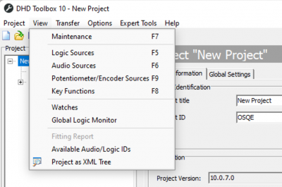
- Open Toolbox10.1. It has an integrated Window that can list all devices. The DHDCS is not used anymore.
- Press F7 or click
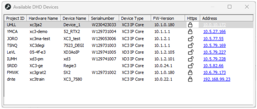
View>Maintenance - The Device List opens up and displays all devices discovered in the network.
- Click on the Device's IP address in the list
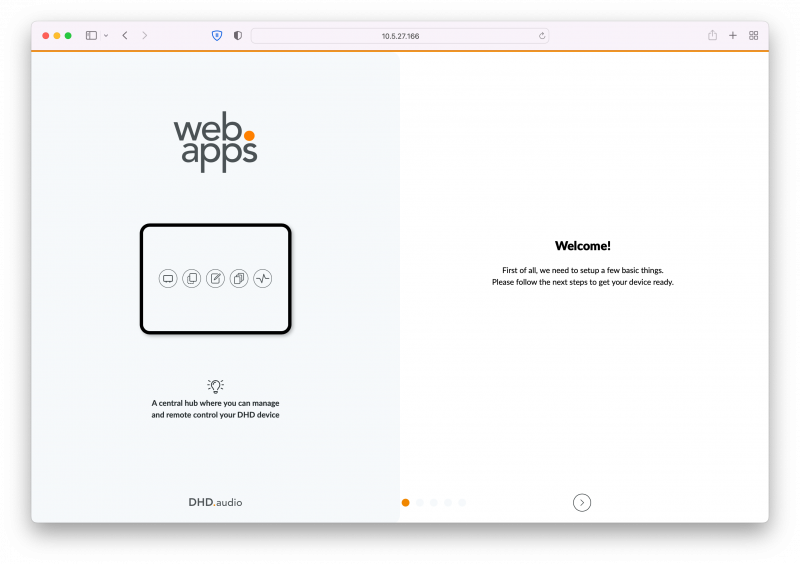
- Your web-browser opens with the device's IP address and will access WebApps
A new Core will then show the initial Onboarding Process to configure an admin password or individual IP settings.
Set Up the Device
Onboarding
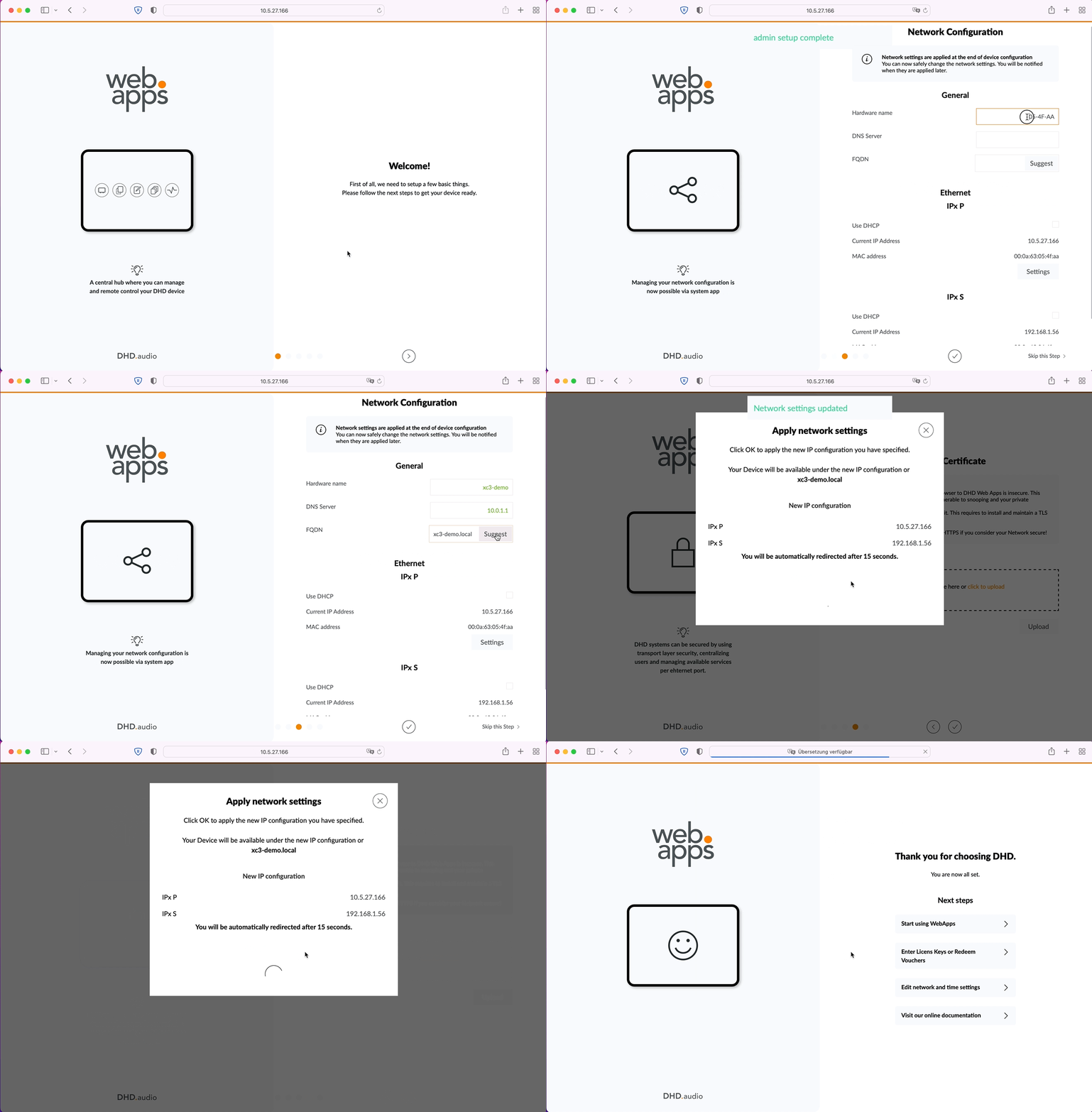
When WebApps are first launched, a onboarding sequence will be displayed. It consists of the following steps:
- Setup admin user
- Setup device network interfaces (optional)
- Setup TLS (optional)
- Apply network configuration
- Launch WebApps
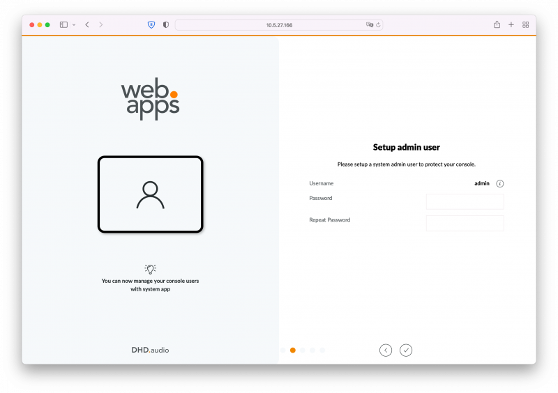
Setup Admin User
First, choose a admin user password. This will be required to add more users to the system and for system administration.
Important
Admin user has access to all setup and configuration functions, so we recommend using a strong password.
Tip
You can add more users later on. After login, go to System App > User Management and click Add User. See also Toolbox setup & user management for user group and rights assignment.
After setting admin user password as desired, click the ✓ button on the bottom of the page to continue.
Setup Device Network Interfaces
No network settings are applied immediately. After completing network and TLS setup, you will be asked to apply the settings.
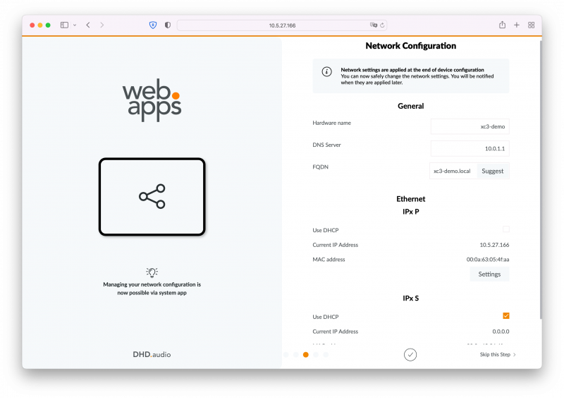
On the network configuration page, first enter a hardware name. The device will later be accessible under [Hardware Name].local, as this is published as mDNS to the local network, if supported by your network environment.
Afterwards, enter a DNS server. It is required to address other devices or services on the network by name instead of IP address. Also, setup a FQDN. If not sure what to set, click Suggest and use the recommended setting. FQDN is only required to be set correctly when using a TLS certificate.
Then, setup the network interfaces. Within each network interface entry, click Settings button to access full IP configuration.
Important
Make sure that all network interfaces are configured to a different subnet. For XC3 core a good example would be:
- IPx P: 10.0.0.0/8 (e.g. IP: 10.0.2.23; Subnet mask: 255.0.0.0)
- IPx S: 192.168.1.0/24 (e.g. IP: 192.168.1.12; Subnet mask: 255.255.255.0)
A MISCONFIGURATION would be:
- IPx P: 10.0.0.0/8 (e.g. IP: 10.0.2.23; Subnet mask: 255.0.0.0)
- IPx S: 10.0.0.0/8 (e.g. IP: 10.5.2.23; Subnet mask: 255.0.0.0)
This would lead to unpredictable behaviour of the device within the network.
Note
On XD3, ETH1 and ETH2 behave as virtually the same physical interface, therefore they share the same network configuration. This is for redundancy purposes.
Note
In redundant XD3 systems, ETH 3 must be used as direct (point-to-point) connection between main and backup core. DHD recommends the following network configuration:
- Main XD3:
- IP address: 172.16.0.1
- Subnet Mask: 255.255.255.0
- Backup XD3:
- IP address: 172.16.0.2
- Subnet Mask: 255.255.255.0
After setting all network configuration as required, click the ✓ button on the bottom of the page to continue.
Setup TLS Certificate
Note
This step is optional. You can add a TLS certificate later. To skip, click the ✓ button on the bottom of the page.
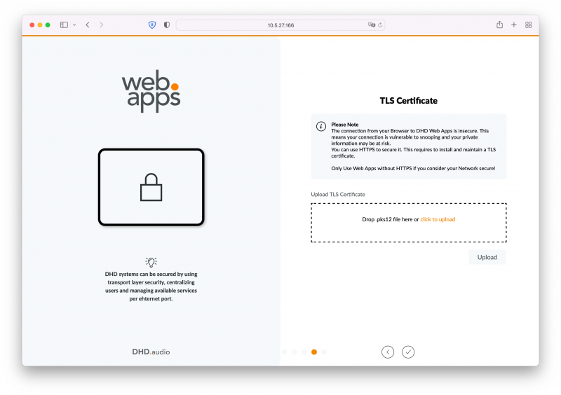
By default, the connection from your browser to DHD Web Apps is insecure, because the device only uses HTTP instead of HTTPS This means the connection is vulnerable to snooping and your private information, e.g., the admin password, may be at risk.
You can use HTTPS to secure it. This requires to install and maintain a TLS certificate.
Important
Only use Web Apps without a TLS certificate (HTTPS) if you consider your Network to be secure!
To upload a TLS certificate, drag and drop a certificate in .p12 file format into the drag and drop area or use click to select with your file browser and select a file to upload.
After selecting a file, click Upload. The file will be uploaded and checked if valid and usable for the device.
Note
A .p12 file is required, because it contains both elements of the certificate chain, public and private key. You can use third party converter software to generate .p12 files.
Important
The .p12 file must meet the following technical requirements, otherwise the validation after the Upload will be not successful:
- internal archive file format: PKCS#12
- file must not be protected with an extra
export passwordwhile it is generated / exported
After uploading, more informations will be displayed about the certificate details. It is important that the FQDN you entered in Setup Device Network Interfaces matches the DNS name displayed here. Also note the Valid until output.
Important
If you decide to upload a TLS certificate later on, you can do so on System App > Network Settings > Security Settings page. Please keep in mind that a restart of the webserver on System App > Service page is required afterwards.
After setting all network configuration as desired, click the ✓ button on the bottom of the page to continue.
Apply Network Configuration
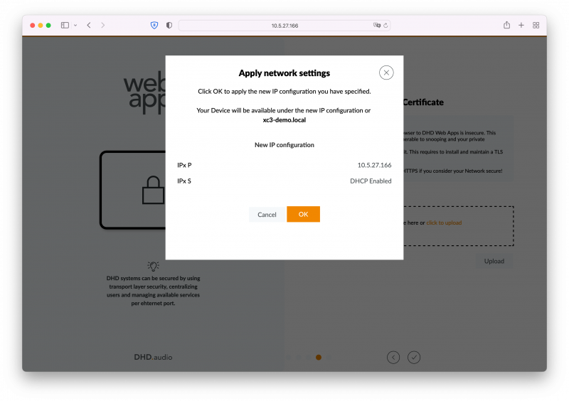
After confirming the TLS certificate settings, a dialog box will appear, summarizing all new network settings. If the configuration is good, click OK. New network settings will now be applied. You will be redirected within 10-20 seconds to the new [Hardware Name].local address. This will only be successful if yor PC's network configuration matches the device's new network configuration.
If you want to correct some network settings, click Cancel and < Buttons at the bottom to redo configuration until correct.
If you already prepared your device to work with your new network environment, wait some additional seconds. You can now unplug it and connect it to your network and use it as intended.
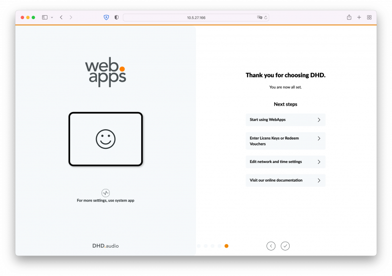
You are redirected to the final onboarding page, providing you with useful links to next steps and functions. If network configuration changed, the next time you open the device's web interface, WebApps will launch.
Next Steps
After performing the initial setup, the following additional steps might be required:
- Setup NTP Time Server
- Setup Timezone and DST
Start Configuration and Use the Device
If not configured already, use Toolbox to configure your device or start using the device and the device's WebApps.


