Table of Contents
Console
On the Console page you can configure keys, TFT views and the OLED display on the central module.
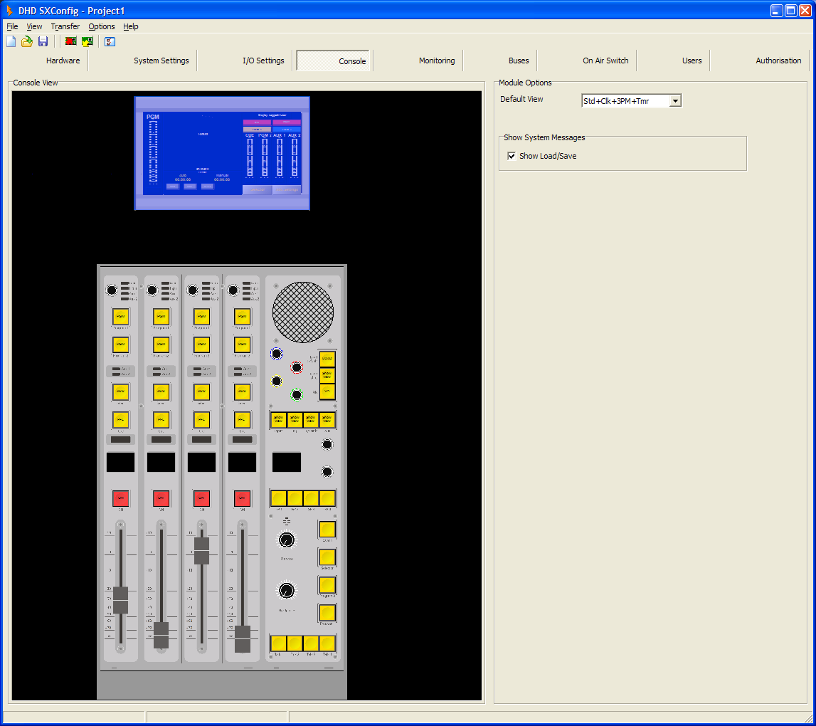
To configure an element, select it by clicking in the Console View area. Its options are shown in the area to the right of the Console View area.
TFT/Touch Display Element
| option | desctiption |
|---|---|
| Default View | In this list, all available default TFT views are shown. Select a default view from the list. (For differences between the default views see Default views table) |
| Show System Messages | Select the check box in front of the system message to enable it on the TFT/Touch Display. |
Key Element
| option | desctiption |
|---|---|
| Number | Shows the generated number of the selected key: <name of fader module>.Key<key number on this module> |
| Function | Shows the assigned key function. To change the default key function of a key, follow these steps: 1. Select a key on the console view. 2. In the View menu, select Key Functions. The Key Functions window opens.3. In the Key Functions window select a Key Function from the list and click Select. |
| Label | Enter a name for the key. This name will be shown in the Console View and will be available for the label print feature. |
| Colors | Depending on the selected key function, you can define here, with which color the key shall light up according to the lamp source. On is the color if the function is enabled, Off if the function is in inactive condition. For the last case, mostly the Off option is used, for example the key does not light up. Depending on the selected key function, you find also different names in the Lamp Source column, for example Standby, Available, Busy, Owned, Layer A, Layer B or the name of the selected lamp source. You can define the colors red and yellow. You can define flashing colors for the keys. Select the check box, in the Colors area. To change the logic source for a color, select an entry in the Lamp Source column and click Source. The Logic Sources window opens. In the Logic Sources window, select a logic source from the list and click Assign. |
| Toggle Mode | Momentary - The function is enabled as long as the key is pressed.\\ Toggle - This key is stay put.\\ Timed Toggle - This key is stay put (short press) or spring return (long press). |
OLED display on central module 52-1010
| option | desctiption |
|---|---|
| Display 1 | Display 1 is the display number and shown only for information. |
OLED displays on fader modules
| option | desctiption |
|---|---|
| Line | This column shows the numbers of lines in the OLED display. |
| Display Content | You can select for each display line, which parameter are shown. You can select between the following parameter: • (none) - nothing will be displayed in this line.• Ch Name (Chrs 1-8) - The characters 1 to 8 of the channel name are shown in this line.• Ch Name (Chrs 9-16) - The characters 9 to 16 of the channel name are shown in this line.• Ch Timer - Shows the channel timer in this line.• DSP Icons - Shows DSP icons, for indication of used DSP features (Gain, EQ, Dynamics), Pan/Bal, and input level.• Encoder function - Shows the function of the encoder, for example Pan/Bal or Gain.• Encoder Param. - Shows the parameter for the encoder function, for example Pan or AGain.• Encoder Value - Shows the value of the encoder, which is selected in the Parameter column. |
| Parameter | If Encoder function, Encoder Param. or Encoder Value is selected, you can select in this column the associated encoder. |
| Follow Layer (no effect on 52/SX, because only one layer is available) | Active - shows the values for the active (1st layer) fader channelHidden - shows the values for the hidden(2nd layer) fader channel |
Monitoring keys - Extern, Selector, Program 2, Program 1
Press the Extern key, to monitor a preconfigured audio source. This source can be any audio source, that is available in the mixing system. To set the audio source for this key, follow these steps:
- In the Consol View, select the Extern key (key 8).
- In the
Key Optionsarea, click theSelectbutton, next to theLeft Sourcebox, theAudio Sourceswindow opens. - In the
Audio Sourceswindow, select an audio source and click assign. - Now you can select the audio source for the right channel and drag it directly to the
Right Sourcebox.
Press the Selector key, to monitor an audio source which can be selected during operation via the TFT Touch Display. This source can be any audio source, that is available in the mixing system. To set the audio source for this key, follow these steps:
Press the Program 2 key, to monitor the Program Bus 2 or, if the console is used with an Off-Air bus, the Off-Air/Recording bus.
Press the Program 1 key, to monitor the Program Bus 1.
General Purpose keys - GP1, GP2, GP3, GP4
You can configure these keys as User Defined Key or Potentiometer key.
User defined:
- By right-clicking
(not assigned)in theLamp Sourcecolumn, you can either select the key itself as a source or select any source from thelogic sourceswindow. - You can use the key as a logic source in many ways, for example for the On-Air Switch or routing to GPOs.
- You can change the sequence of the three rows in the Colors area. Drag a row in the
Lamp Sourcecolumn to its new priority place. - The LED with higher priority lights up if its lamp source is active; two colors can't light up at the same time!
- The LEDs of the keys can also be used to show a condition without having assigned a key function. This is useful for signalisation via GPIs.
Potentiometer:
- In the
Potentiometerlist you can choose from virtual potentiometers, which can be assigned to an encoder in your central module by pressing this key. - In the
Encoderlist you can chose the encoder to which the virtual potentiometer will be assigned. (F1=upper encoder, F2=lower encoder)
All available virtual potentiometers and their function are shown in the following table:
| potentiometer | function |
|---|---|
| Monitor 2 | set volume for signal “Monitor 2” |
| HP 2 | set volume for signal “HP 2” |
| Monitor 3 | set volume for signal “Monitor 3” |
| Monitor 4 | set volume for signal “Monitor 4” |
| CUESPLIT | set the ratio between the PFL signal and the monitoring signal |
| CUE/TB | set volume for the speaker in the central module |
| AUX 1 | set volume for bus “AUX1”, Aux 1 Master settings are also available via AUX Master view on the TFT Touch screen |
| AUX 2 | set volume for bus “AUX 2”, Aux 2 Master settings are also available via AUX Master view on the TFT Touch screen |
Keys - Talk 1, Talk 2, Talk 3, Talk 4
You can configure these keys only as User Defined Key.
User defined:
- By right-clicking
(not assigned)in theLamp Sourcecolumn, you can either select the key itself as a source or select any source from thelogic sourceswindow. - You can use the key as a logic source in many ways, for example for the On-Air Switch or Talkback.
- You can change the sequence of the three rows in the
Colorsarea. Drag a row in theLamp Sourcecolumn to its new priority place. - The LED with higher priority lights up if its lamp source is active; two colors can't light up at the same time!
- The LEDs of the keys can also be used to show a condition without having assigned a key function. This is useful for signalisation via GPIs.
Default views
In the following table, the differences between the default TFT views are shown.
| view name | standard elements (Std) (PGM peak meter, CUE peak meter, 4 state indicators, navigation buttons, user name) | clock (Clk) | three additional peak meter for PGM 2, Aux 1, Aux 2 (3PM) | timer (Tmr) | sync status indicators |
|---|---|---|---|---|---|
| Std+Clk | X | X | X | ||
| Std+Clk+3PM | X | X | X | X | |
| Std+Clk+3PM+Tmr | X | X | X | X | |
| Std-CUE+Clk | X (without CUE peak meter) | X | X | ||
| Std+Tmr | X | X | |||
| Std+3PM+Tmr | X | X | X | ||
| Std | X | ||||
| Std+Clk+Tmr | X | X | X |
X: the element is available in this view