Fixed Processing
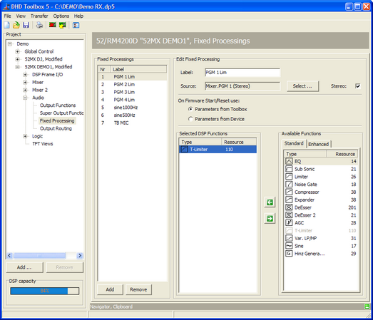
To create and configure fixed processings, select <Device>/Audio/Fixed Processing in the project tree.
Fixed processings are universally applicable, fixed DSP functions to route internal signals for example through limiters, compressors etc. In addition, sine generators can be configured.
You can use every audio signal available on the internal TDM bus as input for a fixed processing: inputs, delays, mixing functions (summing busses, groups, Aux busses), pre-fader signals (fader channel after input processing), clean feeds (n-1 busses), monitor functions, fixed processing, output functions, super output functions and talk outputs. The output of each fixed processing is available as an audio source in the Audio Sources window.
Fixed Processings are internally computed as stereo, but they also can be used mono.
Mixing devices contain a variety of DSP functions by default. Additional enhanced processings require an additional license code that has to be ordered separately.
Important
Fixed Processings can not be adjusted or changed by the mixer interface! The settings can be made with the Toolbox5 software or with the DSP control software of the DHD Operation Manager to be able to change the settings during the runtime.
Available DSP functions
Important
Not all Fixed Processings listed in the tables below are available with 52/XC/XD/XS. See 52-8581 Enhanced DSP Processing license for further details.
The following DSP functions are available for fixed processing:
| standard DSP functions | available in | max. number per fixed processing | option/parameter |
|---|---|---|---|
| Limiter | 52/RM4200D DSP Frame, 52/XR Router | 1 | 1. Threshold: Threshold in the range -20 dBint to +20 dBint (in steps of 1 dB). 2. Release Time: Release time in the range 3 dB/s to 20 dB/s (in steps of 1 dB/s). • The attack time can not be adjusted, it is always set to quick. |
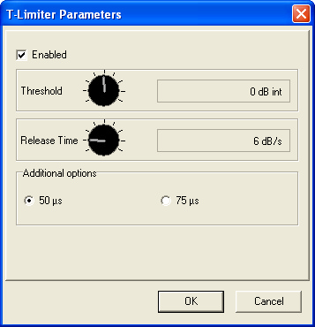
| T-Limiter | 52/RM4200D DSP Frame, 52/XR Router | 1 | • Transient Limiter with 300µs signal pre-delay, that allows to preprocess the signal. 1. Threshold: Threshold in the range -20 dBint to +20 dBint (in steps of 1 dB). 2. Release Time: Release time in the range 3 dB/s to 20 dB/s (in steps of 1 dB/s). 3. Additional Options: If you have configured a preemphasis, you can add this information here to adapt the working mode of the T-Limiter. |
| Compressor | 52/RM4200D DSP Frame, 52/XR Router | 1 | 1. Gain: Output gain in the range of 0 dB to +30 dB (in steps of 1 dB). 2. Threshold.: Threshold in the range -50 dBint to +10 dBint (in steps of 1 dB). 3. Ratio: Ratio in the range of 1.0:1 to 5.0:1 (steps of 0.1). 4. Attack: Attack time in the range of 0.2 ms to 50 ms (8 values). 5. Release: Release time in the range of 0.05 s to 10 s (8 values). |
| Expander | 52/RM4200D DSP Frame, 52/XR Router | 1 | 1. Gain: Output gain in the range of 0 dB to +30 dB (in steps of 1 dB). 2. Threshold.: Threshold in the range -50 dBint to +10 dBint (in steps of 1 dB). 3. Ratio: Ratio in the range of 1:1.0 to 1:5.0 (steps of 0.1). 4. Attack: Attack time in the range of 0.2 ms to 50 ms (8 values). 5. Release: Release time in the range of 0.05 s to 10 s (8 values). |
| EQ | 52/RM4200D DSP Frame, 52/XR Router | 4 | • Equalizer with up to 4 bands. 1. EQ Type: EQ type can be toggled between Bell, Notch, Shelving High and Shelving Low. 2. Gain: Gain in the range -15 dB to +15 dB (in steps of 0.25 dB). Option is ignored if EQ type Notch is selected. 3. Frequency: Frequency in the range 22 Hz to 20000 Hz (60 fixed preset values). 4. Quality: Quality in the range 0.1 octaves to 3.0 octaves (in steps of 0.1 octaves). Option is ignored if EQ type Shelving Low/High is selected. • The toggling of the EQ type is not noiseless! |
| Sine | 52/RM4200D DSP Frame, 52/XR Router | 1 | • Sine generator. 1. Level: Level in the range -80 dBint to +15 dBint (in steps of 1 dB). 2. Frequency: Depending on the Frequency table selection Frequency in the range 22 Hz to 20000 Hz (terz; 60 fixed preset values) or the rows and columns 1 to 4 of the DTMF table (8 fixed preset values).3. Frequency table selection: Here you can choose the frequency scale for the frequency option above. Terz (standard frequencies of a 1/3-octave) or DTMF (dual-tone multi-frequency signaling). |
| AGC (Automatic Gain Control) | 52/RM4200D DSP Frame, 52/XR Router | 1 | 1. Velocity: Control speed in the range 0.3 dB/s to 1.5 dB/s (in steps of 0.1 dB/s). 2. Gain: Max. signal shift in the range 5 dB to 30 dB (in steps of 1 dB). 3. Level: Set output level in the range -20 dBint to 20 dBint (in steps of 1 dB). 4. Freeze: Freeze threshold of the AGC in the range -40 dBint to -20 dBint (in steps of 1 dB), for lower levels, the current or last value is recorded respectively. |
| Sub Sonic | 52/RM4200D DSP Frame, 52/XR Router | 2 | 1. Frequency: Frequency in the range 32 Hz to 200 Hz (17 fixed preset values). • This subsonic filter is a 3rd order high pass filter (18 dB/octave). For other filter orders, please use the function Var. LP/HP. |
| DeEsser | 52/RM4200D DSP Frame | 1 | 1. Ratio: Ratio in the range 1.0:1 to 4.0:1 (in steps of 0.1). 2. Threshold: Threshold in the range 1.0 to 1.8 (in steps of 0.1). 3. Bandwidth: Bandwidth in the range 0.2 to 0.5 (in steps of 0.1). |
| DeEsser 2 | 52/RM4200D DSP Frame, 52XR Router | 1 | 1. Frequency: Frequency in the range 1000 Hz to 20000 Hz (28 fixed preset values). 2. Threshold: Threshold in the range -40 dB to +10 dB (in steps of 1 dB).\\ |
| Var. LP/HP | 52/RM4200D DSP Frame, 52/XR Router | 2 | • Variable filter, high pass or low pass up to 10th order. 1. Filter Type: Filter type can be toggled between HighPass and LowPass. 2. Frequency: Frequency in the range 22 Hz to 20000 Hz (60 fixed preset values). 3. Filter Order: Filter order can be set between 1st order (6 dB/octave) and 10th order (60 dB/octave). • The toggling of the type and filter order is not noiseless! |
| Noise Gate | 52/RM4200D DSP Frame, 52/XR Router | 1 | 1. Attenuation.: Attenuation in the range 0 dB to 30 dB (in steps of 1 dB). 2. Threshold: Threshold in the range -60 dBint to -10 dBint (in steps of 1 dB). 3. Attack: Attack time in the range of 1.0 ms to 200 ms (8 values). 4. Release: Release time in the range of 0.01 s to 2.0 s (8 values). |
Enhanced DSP Processing
For special applications like sound processing for FM transmission you can configure special Enhanced DSP Functions. These functions are enabled using one license code per DSP frame:
| enhanced DSP functions | available in | max. number per fixed processing | option/parameter |
|---|---|---|---|
| Enhancer | 52/RM4200D DSP Frame | 1 | • Stereo Enhancer to improve the stereo sound. 1. Widening: This option allows the widening of the stereo spread. 2. 3D Effect: Creates a stereoscopic effect by adding delayed signals with a latency between 0 ms (0%) and approx. 40 ms (100%). 3. 3D Mix: Controls the ratio of the existing signal and the signal with 3D effect. 0% means no 3D effect and at 100% only the signal with 3D effect is passing. 4. Release: Because of the widening effect, it may happen that the correlation becomes negative. The enhancer Plug-In includes a correlation limiter, that automatically lowers the widening to avoid destructive cancellations. At 0% this limiter is always active. If you higher the release time, negative correlated signals are excepted for a while. |
| Steel Unit 3-Band | 52/RM4200D DSP Frame | 1 | • 3-band compressor with a soft clipper in each band. • The soft clipper limits each band to 0 dB. 1. Low, Mid, High: The settings of the 3 bands are separated on 3 tabs. 2. Compression: Compression in the range 0 dB to +15 dB (in steps of 1 dB). This option increases the compression. It is combined function that can be understood as a combination of threshold, make-up gain and compression ratio. With a rising compression value, the threshold is decreased by this value, the make-up gain is increased by the same value and the compression rate is increased for the signals between the threshold and 0 dB. Therefore, programmed compression response curves with a soft knee characteristic are used. 3. Gain: Gain in the range 0 dB to +20 dB (in steps of 0.2 dB). This is the input gain of the compressor. Use this option to increase the input level of the compressor to exceed the threshold with lower signals. 4. Mix: Mix in the range -20 dB to +20 dB (in steps of 0.2 dB). Here you can adapt the level of the band in the output signal of the steel unit. 5. Release: Release time of the compressor in the range of 0.05 s to 10.0 s (8 values in s: 0.05, 0.1, 0.2, 0.5, 1.0, 2.0, 5.0, 10.0). |
| Steel Unit 4-Band | 52/RM4200D DSP Frame | 1 | • 4-band compressor with a soft clipper in each band. • The functionality of the 4-band steel unit is identical to 3-band steel unit, but with a second Mid band that is shown in a fourth tab. |
| Soft Clipper | 52/RM4200D DSP Frame | 1 | • The soft clipper is a limiter with soft knee functionality. • Max. Output Level: Max. Output Level in the range -20 dB to +20 dB (in steps of 1 dB). |
| Adaptive Preemphasis | 52/RM4200D DSP Frame | 1 | • Adaptive Preemphasis (for FM transmitters). 1. Deemphasis: Activate this option if you want to remove an existing preemphasis from the signal. 2. Timing Options: Select one of the standard values (50 µs or 75 µs) that should be used for the preemphasis/deemphasis. |
| 90˚ Filter | 52/RM4200D DSP Frame, 52/XR Router | 1 | • Mono creation without shifting the medium frequencies. |
| Profanity Delay | Only 52/XC/XD/XS | 1 | See Profanity Delay |
| Loudness AGC | Only 52/XC/XD/XS | 1 | Parameter set: See AGC. |
| Pink Noise Generator | Only 52/XS, 52/XC, 52/XD | 1 | Generates pink noise. |
| Delay 1s | 52/XR Router | 1 | 1. Delay time: Adjustable between 0 s and 1 s in steps of 1 ms. |
| Delay 10 s | 52/XR Router | 1 | 1. Delay time: Adjustable between 0 s and 10 s in steps of 1 ms. |
| Hinz Generator | 52/RM4200D DSP Frame, 52/XR Router | 1 | • Sound signal for traffic broadcast recognition (Germany only). |
To use the extended functions, you have to order the software license 52-8581 Enhanced DSP Fixed Processing. To be able to adjust the settings during the runtime, you also need the 52-8565 DSP Control Software, which has to be ordered additionally.
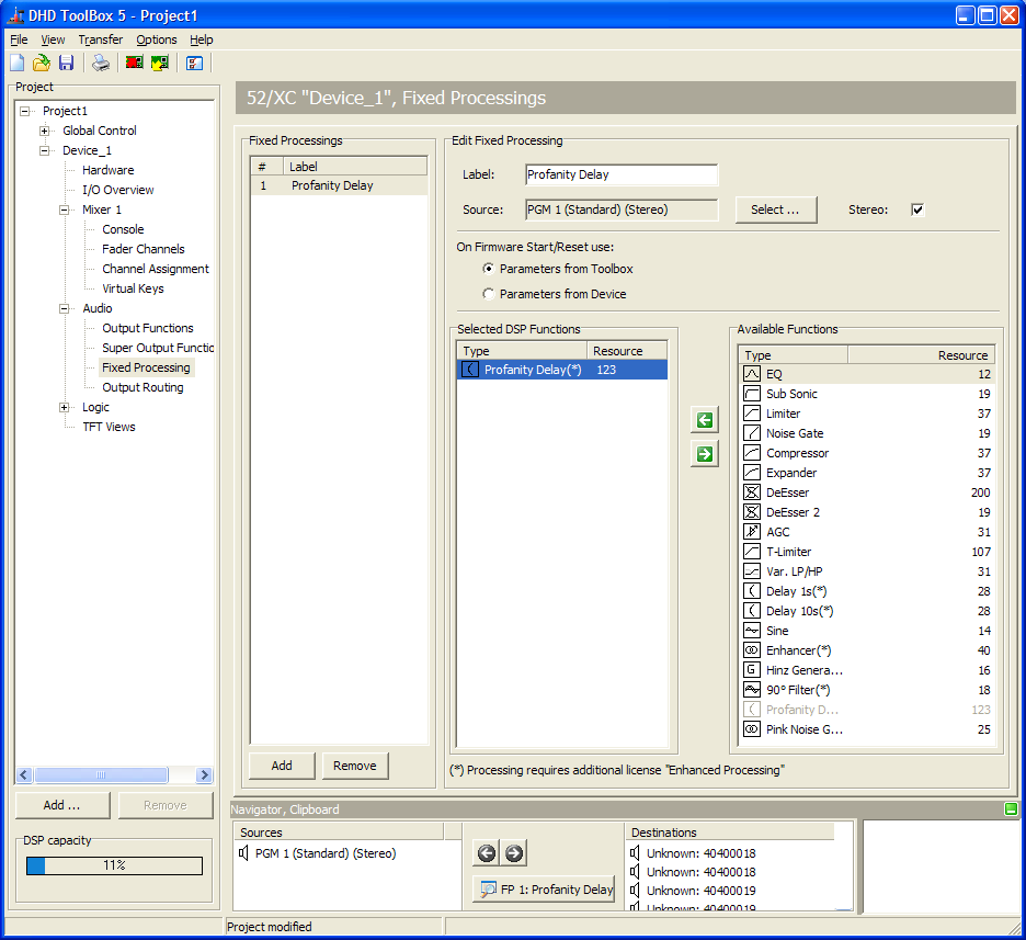
Configuring Fixed Processings
To create and configure a fixed processing, follow these steps:
- To create a new fixed processing, in the
Fixed Processingsarea, clickAdd. - To change the name for a selected fixed processing, in the
Edit Fixed Processingarea, enter name in theLabelbox. This label can be up to 16 digits long. - To select an audio source as input for the processing, click
Select. TheAudio Sourceswindow opens. - In the
Audio Sourceswindow, select the desired audio source and clickAssign. Alternatively, you can double-click on the audio source or drag it to theSourcebox.Note
If you use a generator function for the fixed processing, you don't need to assign an audio source. If an audio source is assigned anyway, it will be ignored! - If you select the
Stereocheck box, the subsequent channel is selected automatically, in most cases the right channel of a stereo signal. Apart from this, the fixed processing is also shown as a stereo signal in theAudio Sourceswindow. - To assign a DSP functions to a selected fixed processing, select the desired DSP function in the Available Functions list and click . Alternatively, you can double-click on the desired DSP function or drag it to the
Selected DSP Functionslist. - To change the parameter of a DSP function, in the
Selected DSP Functionsarea, double-click on it, a parameter window opens. In this window the respective parameters for each DSP function are shown. (For a list of parameters see fixed processings)
All levels generally relate to the internal reference level of 0 dBint. For example, if a limiter at a digital output configured with a headroom of 9 dB should trigger exactly at the maximum level of 0 dBFS, you have to set them to 9 dBint.
In the Edit Fixed Processing area, you can also select which parameter data are loaded in case of a firmware start/reset. You can choose between Parameters from Toolbox or Parameter from Device. The parameters from Toolbox are the parameters which are set by default in the Toolbox5 Config file. The parameters from the device are the values which are maybe changed by a DSP control software.
Note
You can assign up to 10 DSP functions to a single fixed processing.
For the configuration of a fixed processing, you have the following options:
- To remove a DSP function from the
Selected DSP-Functionslist, select the DSP function and click . Alternatively, you can also drag the DSP function from the
 Selected DSP Functionslist to theAvailable Functionslist. - The order of the entries in the
Selected DSP Functionslist (top to bottom) also indicates the signal path. You can change this order by dragging a DSP function to a new position in the list. - To remove a selected fixed processing from the
Fixed Processingslist, clickRemove.
Number of DSP-Processings
Each DSP-Module RM420-848L and RM420-848M is able to calculate 24 stereo DSP processings. Because of that up to 72 DSP processings per device are possible. Because the dual MADI modules RM420-422S occupy some channels on the TDM bus system, that are normally used for DSP processings, the usage of these modules can influence the DSP load.
Apart from that, the available DSP processings are used for fixed processing and for fader input processing. When configuring the fader modules, the corresponding number of DSP processings is automatically occupied .
The following table shows the total number of DSP processings for the different combinations of DSP modules and dual MADI modules:
| combination | RM420-848L - 24 stereo DSP processings each | RM420-848M - 24 stereo DSP Processings each | RM420-848M + RM420-422S - 12 stereo DSP Processings | number of available stereo fixed processings = DSP processings - (minus) number of faders |
|---|---|---|---|---|
| A | 1 | 24 - number of faders | ||
| B | 2 | 48 - number of faders | ||
| C | 1 | 24 - number of faders | ||
| D | 2 | 48 - number of faders | ||
| E | 3 | 72 - number of faders | ||
| F | 1 | 12 - number of faders | ||
| G | 2 | 24 - number of faders | ||
| H | 1 | 1 | 36 - number of faders | |
| I | 3 | 36 - number of faders | ||
| K | 1 | 2 | 48 - number of faders | |
| L | 2 | 1 | 60 - number of faders |
The total number of fixed processings is limited by the maximum DSP capacity available in the system. The DSP capacity is indicated below the project tree and constantly updated during the configuration process. The DSP capacity bar shows the DSP load of the device currently selected in the project tree. If the load reaches 100%, the color of the bar changes from blue to red. In this case, if you try to load a Config to the device, an error message is shown. Uploading a Config is only possible if the DSP load is under 100%.
Important
When creating the fixed processings, keep in mind that they affect the DSP load of the whole system. Therefore, do not create more fixed processings than necessary to save the DSP resources for other applications.
Profanity Delay
The Profanity Delay is available for all Series 52 mixing consoles when using 52/XS Cores 52-1801/52-1804, 52/XC Cores 52-740x or 52/XD Cores 52-744x.
Important
- The Profanity Delay is not (and will not be) available for the RM4200D DSP Frame or 52/XR MADI Router!
- TB5 Version 7.1.4 or higher is required to use Profanity Delay function.
- The Hardware needs the license 52-8581 Enhanced DSP Processing (necessary for all 52/XC Cores, 52/XD Cores, 52/XS Cores).
- 52/XS Core hardware additionally requires the license 52-1950 XS Core extended feature upgrade to be able to configure the function and the push buttons
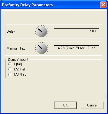
The profanity delay provides a delay time between 1 and 20 seconds with parameters for the minimum pitch and the dump amount.
To configure the Profanity delay in the Toolbox5 software, follow these steps:
1. In the project area, select your <Device>. On the Options tab, in the Licensing area, select the Use Enhanced Processings check box.

2. In the project area, select <Device>/Audio/Fixed Processing. Assign the profanity delay to a Fixed Processing and assign, for example PGM1 as audio source.
3. In the Select DSP Functions area, double-click on Profanity Delay. The Profanity Delay parameters window opens.
- In the
Delayarea, select a profanity delay time between 1 and 20 seconds. - In the
Minimum Pitcharea, select the pitch for fade in and fade out (lower pitch is nearly unhearable, but takeslonger time) - In the
Dump Amountarea, select if thefull (1)delay memory,half (1/2)of the delay memory or athird (1/3)of the delay memory will be dumped when pressing the dump push button on the control surface.
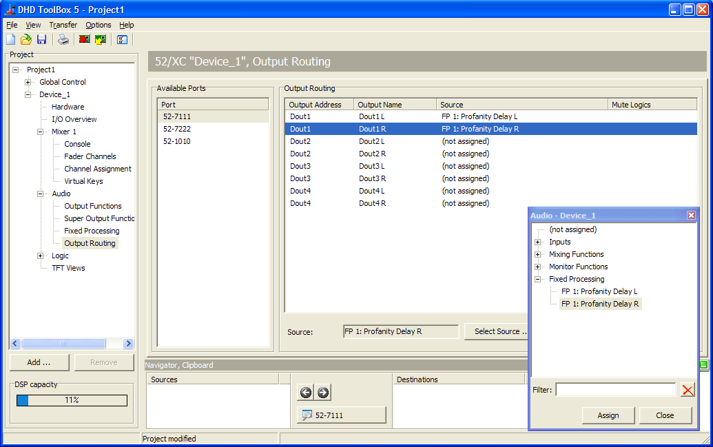
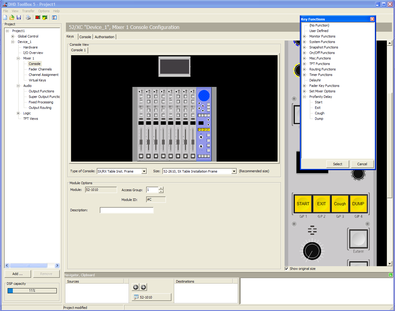
4. In the project area, select <Device>/<Mixer>/Console. On the Keys tab, select a push button in a central control module to assign one of the profanity delay key functions from the Key Functions window. You can also use buttons on the TFT/Touch display.
5. In the project area, select <Device>/Audio/Output Routing. In the Output Routing area, select an audio output and assign the profanity delay Fixed Processing as Source for this output.