52/TX control module (52-1156)
The 52/TX control module 52-1156 is a table top module with a 10.1“ TFT IPS Touch Display (1), 6 push buttons (12 and 13), 2 potentiometers (14), Mic input (XLR), Headphones output (XLR/6.3 mm jack combo), integrated talkback microphone and loudspeaker.
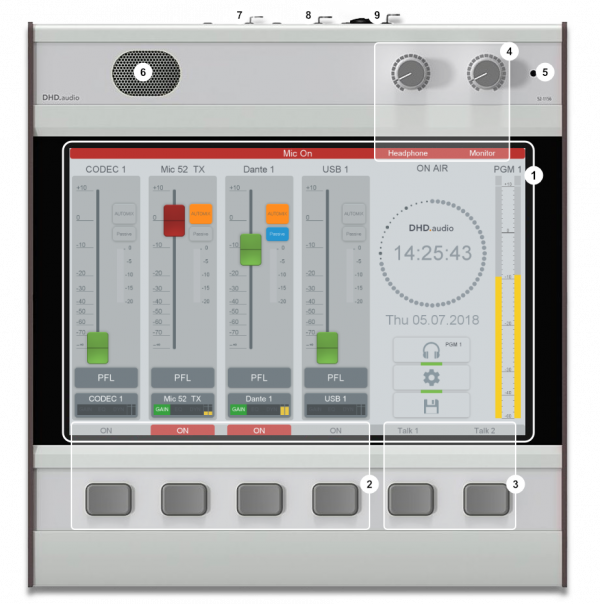
1. The TFT/Touch Display shows diverse pre-set TFT pages. These pages show, for example faders, peak meters, correlation display, clock, stopwatch and setting of EQ, dynamics unit, snapshots and other parameters. The main page can be changed to other Mixer Modes on the Settings page in the user interface.
This TFT display is not only able to show information. Due to it is sensitive to touch, you can use views with buttons to control functions via the TFT screens.
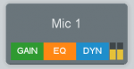
2. On/ Off Buttons for the fader channels. The current state will be shown in the TFT display. If the label is red, it is On, if it is grey it is Off.
3. It is possible to configure this talk keys for a simple talkback, for example to a sound booth or an additional mixing console.
4. Professional high-grade volume potentiometers for Headphone (headphones output at 52-1156 rear) and Monitor speaker (Talkback speaker in 52-1156, when PFL is active).
5. integrated Talkback microphone
6. integrated Talkback loudspeaker
7. APC port
Use this port to connect this 52/TX control unit (52-1156) to the 52-1830 DSP I/O core, see Connecting modules to the 52/XS I/O Core.
8. Microphone input
9. Headphone output
Mixer Mode descriptions
The default configuration that is delivered with the 52/TX Bundle has 3 mixer modes with different main pages:
- Mixer Mode (Default) - shows a simple mixer layout with standard functions like PFL, Access for channel parameters, Automix.
- Basic Mode - shows a basic 2-channel-setup without faders, functionality reduced to a minimum.
- Mixer Advanced - shows an mixer layout with more functions in direct access and additional gain reduction meter for Compressor, Expander and Limiter.
Mixer Mode
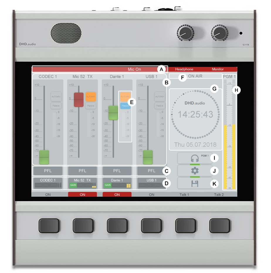
A Mic On (Red Light) signalisation. If a fader with a microphone input is ON, the top bar will light up in red.
B Use the fader to control the audio level from -∞ to 0 dB with an additional gain of +10 dB. Above the fader the channel name is shown.
C Press this PFL button to route the pre fader signal of a fader channel to the PFL bus.
D Access button on TFT Touch display.
With this button you can select a channel, on which you want to make further settings. If the button is pushed, and a TFT settings page is selected, you can see the associated settings, for example EQ settings on the TFT display. All changes belong to the selected fader channels. To deselect the fader channel, push the Select key again or select another fader channel by pushing the associated select key.
This Access button also provides additional information about the channel below, these are: the channel name, the used DSP functions, an input meter and the current gain value.
E Automix fader section
Activate the Automix button to activate the automix function for this fader, see Automix. When you activate the Passive button additionally, a ducking function will be realised on that channel. That means, that a other automix channels are lowering the level of this passive channel, but the passive channel has no influence on the other channels.
The meter shows the current gain reduction if automix is active on that channel.
F ON AIR signalisation Will light up red, if the On-Air switch on the settings page is activated.
G The clock shows NTP time. This needs a configured NTP server, see Configure the time server
H Program level meter This meter shows the current Program 1 level.
I Monitor Selector
Shows the currently selected monitor signal. By pressing this button, you can select other monitoring signals from a list.
J Settings
Push this button to go to the settings page. There you can change the mixer mode, PFL operation modes, color schemes and brightness settings.
K Snapshot
Push this button to go to the Mixer Snapshot page. There you can save or load mixer snapshots.
Basic Mode
The Basic mode features 2 channels. Each channel has a small list of sources that can be chosen for the channel. There is no fader in the channel, to send the channels to the Program Bus, press the ON button below the display. You can use automix (see Automix) for automatically mixing the sources together.
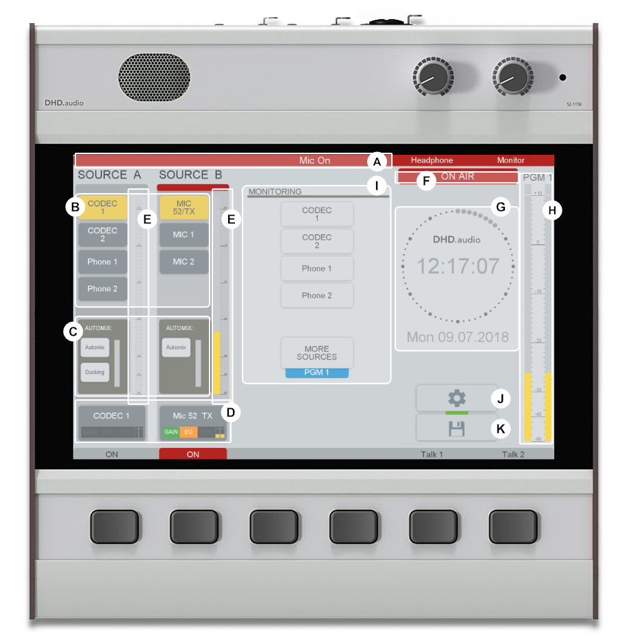
A Mic On (Red Light) signalisation. If a fader with a microphone input is ON, the top bar will light up in red.
B Input selection Both channels have an direct input selection area (see Direct Input Select key function with pre-set source signals. You can select one of these source.
C Activate the Automix button to activate the automix function for this fader, see Automix. When you activate the Ducking button additionally, a ducking function (Passive Mode) will be realised on that channel. That means, that a other automix channels are lowering the level of this passive channel, but the passive channel has no influence on the other channels. The meter shows the current gain reduction if automix is active on that channel.
D Access button on TFT Touch display.
With this button you can select a channel, on which you want to make further settings. If the button is pushed, and a TFT settings page is selected, you can see the associated settings, for example EQ settings on the TFT display. All changes belong to the selected fader channels. To deselect the fader channel, push the Select key again or select another fader channel by pushing the associated select key.
This Access button also provides additional information about the channel below, these are: the channel name, the used DSP functions, an input meter and the current gain value.
E Input channel meter
F ON AIR signalisation Will light up red, if the On-Air switch on the settings page is activated.
G The clock shows NTP time. This needs a configured NTP server, see Configure the time server
H Program level meter This meter shows the current Program 1 level.
I Monitoring Selector
By default the PGM signal will be monitored. To select another signal you can choose one from the four fast select signals or tap MORE SOURCES to select additional monitoring signals from a list. The blue label below the MORE SOURCES button shows the currently selected monitor signal.
J Settings
Push this button to go to the settings page. There you can change the mixer mode, PFL operation modes, color schemes and brightness settings.
K Snapshot
Push this button to go to the Mixer Snapshot page. There you can save or load mixer snapshots.
Advanced Mixer
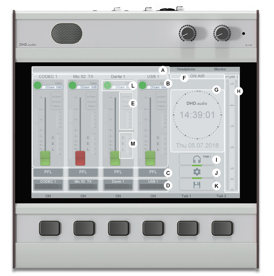
A Mic On (Red Light) signalisation. If a fader with a microphone input is ON, the top bar will light up in red.
B Use the fader to control the audio level from -∞ to 0 dB with an additional gain of +10 dB. Above the fader the channel name is shown.
C Press this PFL button to route the pre fader signal of a fader channel to the PFL bus.
D Access button on TFT Touch display.
With this button you can select a channel, on which you want to make further settings. If the button is pushed, and a TFT settings page is selected, you can see the associated settings, for example EQ settings on the TFT display. All changes belong to the selected fader channels. To deselect the fader channel, push the Select key again or select another fader channel by pushing the associated select key.
This Access button also provides additional information about the channel below, these are: the channel name, the used DSP functions, an input meter and the current gain value.
E Automix fader section
Activate the Automix button to activate the automix function for this fader, see Automix. When you activate the Passive button additionally, a ducking function will be realised on that channel. That means, that a other automix channels are lowering the level of this passive channel, but the passive channel has no influence on the other channels.
The meter shows the current gain reduction if automix is active on that channel.
F ON AIR signalisation Will light up red, if the On-Air switch on the settings page is activated.
G The clock shows NTP time. This needs a configured NTP server, see Configure the time server
H Program level meter This meter shows the current Program 1 level.
I Monitor Selector
Shows the currently selected monitor signal. By pressing this button, you can select other monitoring signals from a list.
J Settings
Push this button to go to the settings page. There you can change the mixer mode, PFL operation modes, color schemes and brightness settings.
K Snapshot
Push this button to go to the Mixer Snapshot page. There you can save or load mixer snapshots.
L Gain encoder
You can change the digital gain for each channel directly. To increase the values tap on the colored wheel and move to the finger upwards or to the right. To decrease the values tap on the colored wheel and move to the finger downwards or to the left.
M Gain Reduction
This gain reduction meter shows the gain reduction summed up for the channel DSP processing Compressor, Expander and Limiter.
Access View
The Access view allows to control parameters for each fader channel, for example gain, routing, panning, DSP processing and input source. To show the Access view, tap on the Access button of the desired channel.
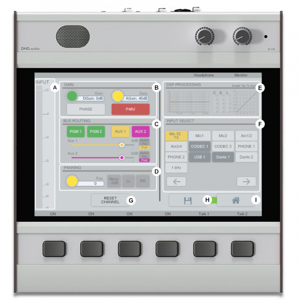
A Input channel meter
Depending on the source, it will be shown as a mono or stereo level meter.
B Gain
The green encoder (left) allows to adjust digital gain value. When a microphone signal source is selected the yellow encoder (right) allows to adjust the analogue gain value.
To increase the values tap on the colored wheel and move to the finger upwards or to the right. To decrease the values tap on the colored wheel and move to the finger downwards or to the left.
The PHASE button activates a phase reverse (in stereo signals right channel only).
The P48V button activates the phantom power if available for the selected channel.
C Bus routing
You can route the selected signal to different busses, by activating the corresponding buttons. All routings are active by default.
The sliders for Aux 1 and Aux 2 allow to adjust the Aux send level for the selected channel. You can also switch the Aux sends also between the modes switch, pre-fader and post-fader (default). (for AUX modes see: Bus functions - Aux Types
D Panning
Use the yellow encoder in that section to adjust the panning/balance value. Additional mono functionalities are available for the other three buttons:
| Button | description |
|---|---|
| Mono -3 dB | • Mono summation -3 dB of the input signals in stereo inputs. |
| LL | • In stereo signals, the left input signal replaces the right. |
| RR | • In stereo signals, the right input signal replaces the left. |
E DSP PROCESSING
This section has 3 parts:
- left: EQ diagram - Double tap on the EQ-diagram to show the EQ Overlay, see Touch EQ Overlay for more information.
- middle: gain reduction meters for Compressor, Expander, Limiter
- right: dynamics diagram - Tap on this diagram to open the Dynamics page, this allows to adjust the channel DSP parameters for Compressor, Expander and Limiter.
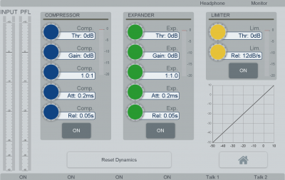 Dynamics page
F INPUT SELECT
When the selected channel is OFF you can change the source in that section. Tap on the selected source to use it for this channel. The currently selected source will light up in yellow. If the channel is ON or the source is already used on a channel the input selection can not be performed.
G RESET CHANNEL button
Tap this button to set default values for this channel for Gain, Panning, EQ and Dynamics.
H Channel Snapshot button
Tap this button to save the channel parameters into a channel snapshot. This channel snapshot can be loaded on other channels to recall the same parameter set.
I HOME button
Tap this button to leave the Access view and show the main page.