Table of Contents
Synchronization
Clock synchronization is based on PTPv2, a protocol to distribute absolute time in IP networks. A network can contain several PTP master clocks, separated in different PTP domains. AES67 devices streaming to each other need the same PTPv2 clock master respectively be in the same PTP clock domain to work correctly. Furthermore, a dedicated general PTPv2 grand master device is recommended for AES67 network infrastructures. Nevertheless, a AES67 RAVENNA interface can serve as Master if no grand master device with higher PTP priority is available (See Settings and Parameters).
For general synchronization of system date and time, the AES67 RAVENNA interface uses NTP. This is required e.g. for licensing, logging or display elements and has nothing to do with stream synchronization. See NTP Timeservers for more information on NTP in DHD Series 52 devices. See Installation and Maintenance of the Interface for information on how to set an NTP Timeserver.
Important
PTPv2 requires UDP ports 319 and 320 to be open.
Sample Rates
DHD Series 52 devices generally support sample rates of 44.1 kHz and 48 kHz. For compatibility purposes with 3rd party devices, it is recommended to use 48 kHz when using a AES67 RAVENNA interface. Therefore, in simple configuration mode, the interface is set to 48 kHz sample rate automatically.
Device Clocking
The interface can be set as slave or serve as PTPv2 master within the network.
The AES67 RAVENNA interface can be used as clock source for the series 52 core device housing it and connected components.
Note
Using the AES67 RAVENNA interface as clock source is only possible when housed in an XC2/XS2 core device. When housed in an XC2 concentrator, the AES67 RAVENNA interface can not serve as a sync source for the core device.
PTPv2 Sync
In general, AES67 devices need to be synced using PTPv2. Any AES67 RAVENNA interface can serve as PTP master. PTPv2 selects the best clock master available using the Best Master Clock Algorithm defined in IEEE 1588. This is useful for backup purposes of uninterrupted audio on running streams.
To configure the AES67 RAVENNA interface as PTPv2 master:
- In
Simplemode and using only DHD devices, checkPreferred Masteroption and make sure, no other device hasPreferred Masterenabled. This will set PTP priority to a higher level than devices without this option activated. If no grand master with a higher PTP priority is serving in the network, this device will become master.
- In
Advancedmode, uncheckSlave Onlyoption. The device will enterMasterslavemode. This means the device will serve as PTP master if it has the highest PTP priority in the network. It is recommended to give the device a higher PTP priority than all other devices within the IP network to ensure it serves as master. If a device with higher PTP priority andMasterslavemode is running in the network, the device will become slave again.
Note
For approx. 30 seconds after startup of a AES67 RAVENNA interface, the PTP service will run in Slave Only mode in order to perform a first sync of the PTP clock. After this time the (user) PTP settings are applied.
Sample Rate Converter (SRC)
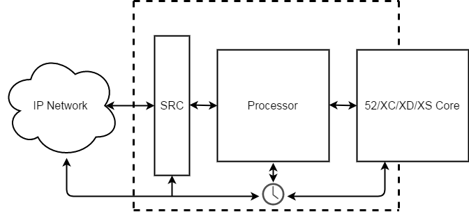
A bidirectional Sample Rate Converter (SRC) is implemented to the interface. Bidirectional means for RX and TX side. The SRC can be switched ON / OFF globally for the AES67 RAVENNA interface via TB8.
When the SRC is ON, the interface is running in asynchronous mode. That means the incoming audio is resampled using device wordclock. See Toolbox8 / Synchronisation on how to set device wordclock source.
When the SRC is OFF, the interface is running in synchronous mode. That means the incoming audio is not resampled using device wordclock. This setting should only be used if the wordclock frequency of the incoming audio is the same frequency used by the DHD AES67 module. This can be the case if this DHD AES67 module has been selected as PTP master clock. This setting can reduce latency by abandoning unnecessary sample rate conversion.
Note
The recommended Setting for the SRC is ON.
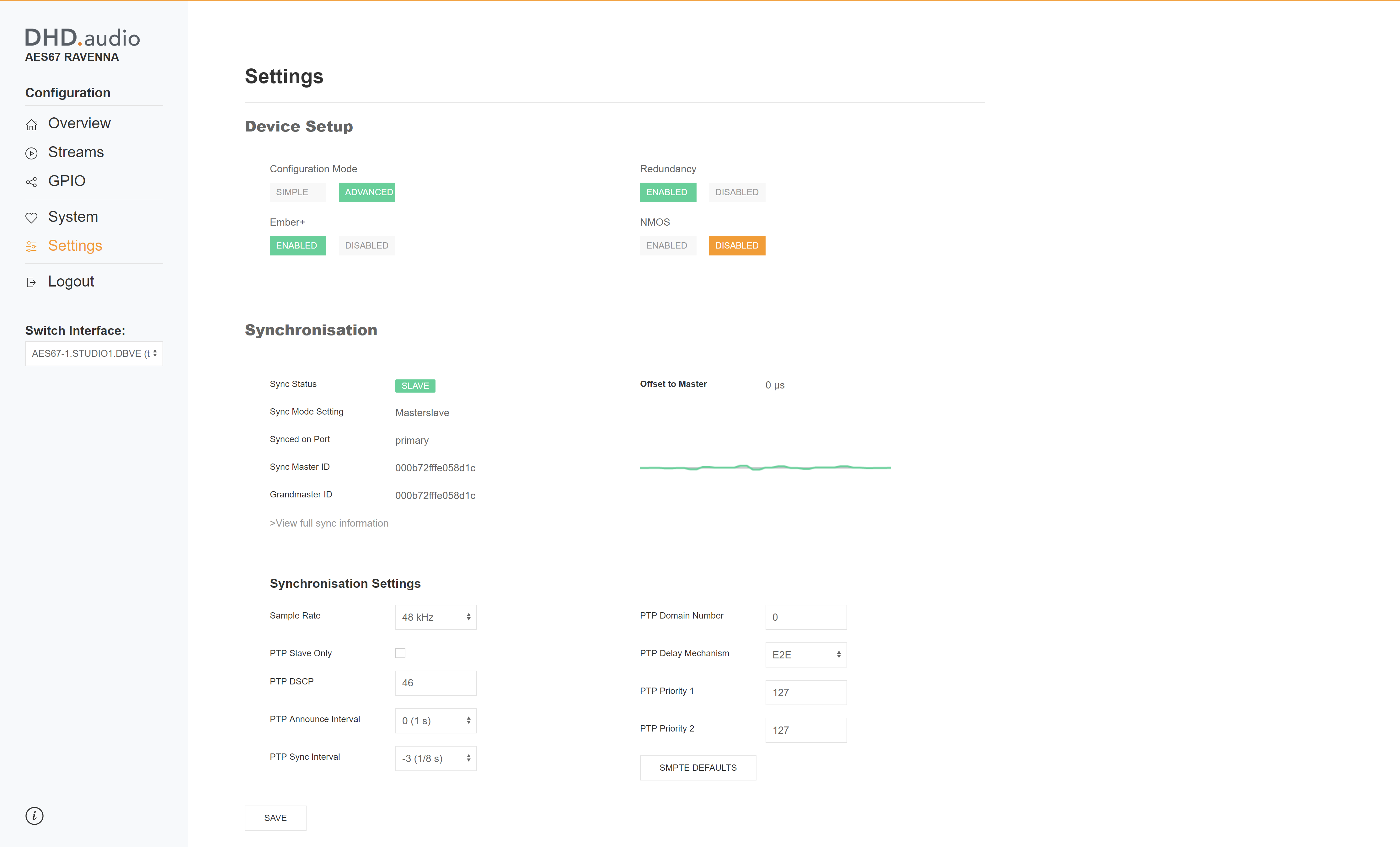
The setting of the SRC can be monitored at synchronization settings section on the web interface. See Configuration via Toolbox for information on how to switch SRC ON or OFF.
Settings and Parameters
Simple Mode
Preferred Master
Set the AES67 RAVENNA interface as preferred PTPv2 master in the IP network. This will set a higher PTPv2 priority level than DHD defaults. When multiple interfaces in the same IP network are set as Preferred master, one of them will be elected as PTP master using Best Master Clock Algorithm defined in IEEE 1588.
Advanced Mode
Sample Rate
Select if the AES67 RAVENNA interface is running with a sample rate of 44.1 kHz or 48 kHz. Default value is 48 kHz.
PTP Slave only
When slave only is checked, sync mode is changed from Masterslave to Slave. See documentation above for more information.
PTP DSCP
Change QoS priority of PTPv2 (sync) packets sent by the AES67 RAVENNA interface.
PTP Announce Interval
Change the interval for PTP announce messages. These messages are, among others, used for the best master clock algorithm to build the PTP priority structure. The interval between PTP announce messages being sent can affect how fast and efficient the grandmaster is elected. This can be a point in possible failover scenarios if PTP announce interval is selected too slow. On the other hand, side, reducing the amount of PTP announce messages (setting a higher PTP announce interval) can help reducing network traffic and load in IP networks with a high amount of devices.
Possible values:
- -2 (1/4s)
- -1 (1/2s)
- 0 (1s) - Default
- 1 (2s)
- 2 (4s)
PTP Sync Interval
Change the interval for PTP sync messages. If the interface is running as slave, this is the requested value: the device requests the interval (and therefore the amount) of sync messages sent by the master to this specific slave. If the requested interval is accepted depends on the PTP master device. Periodical PTP sync messages are required to recalculate clock offset. Reducing the amount of PTP announce messages (setting a higher PTP announce interval) can help reducing network traffic and load in IP networks with a high amount of devices. However, this is only recommended when running an engineered network.
Possible values:
- -4 (1/16s)
- -3 (1/8s) - Default
- -2 (1/4s)
- -1 (1/2s)
PTP Domain Number
Set the PTP domain the interface is assigned to.
| Min value | 0 |
|---|---|
| Max value | 127 |
| Default value | 0 |
PTP Delay Mechanism
Change measurement mechanism of PTP delay. In AES67 case, E2E (End-to-End) is more versatile and recommended. Anyway P2P (Peer-to-Peer) can bring several advantages in engineered networks, such as the grand master clock does not have to respond to Delay_Request messages, which can be useful for networks with many AES67 devices.
For more details and how PTP Delay Mechanisms work, see this Article on meinberg blog.
Possible values:
- E2E (End to End) - Default
- P2P (Peer to Peer)
PTP Priority 1
The PTP Priority 1 value defines the priority of the device to become PTP master in the current PTP domain. The lower the value, the higher the priority. Slave only devices can be set to 255.
| Min value | 0 |
|---|---|
| Max value | 248 |
| Default value | 107 |
PTP Priority 2
The PTP Priority 2 value defines the priority of the device to become PTP master in the current PTP domain. This is one of the last decision points on the PTP Best Master Clock Algorithm. If e.g. two devices have the same parameters such as Priority 1, Clock Class, Clock Accuracy and Clock Variance, the PTP Priority 2 value decides as a last resort.
| Min value | 0 |
|---|---|
| Max value | 248 |
| Default value | 107 |
SMPTE Defaults
Set SMPTE compliant defaults as defined in AES R16. See R16 Compliance below.
R16 Compliance
AES67 RAVENNA interfaces are interoperable within parameters and ranges recommended in AES-R16-2016. The AES R16 'compares the profiles and identifies features and parameter ranges that should enable interoperability among equipment conforming to the different profiles'1).
On DHD side, the implementation of the proposed attribute values for interoperability between AES and SMPTE profiles was a general objective.
Affected values are:
| Parameter | DHD implementation name | Min from R16 | Max from R16 | Prop. from R16 | DHD default | Further information |
|---|---|---|---|---|---|---|
domainNumber | PTP domain number | 0 | 127 | 0 | 0 | Must be same for all devices |
logAnnounceInterval | PTP announce interval | 0 | 1 | 0 | 0 | Must be same for all devices |
announceReceiptTimeout | 2 | 10 | 3 | fixed by firmware | ||
logSyncInterval | PTP sync interval | -4 | -1 | -3 | -3 | Does not have to be same for all devices |
logMinDelayReqInterval | Greater of -3 and logSyncInterval | logSyncInterval +5 | -3 | Calculated automatically by firmware | ||
(Table based on AES-R16-2016, chapter 5.3.22))

