Table of Contents
Device Menu
Reconnect
The Reconnect command interrupts the TCP/IP connection between the Maintenance PC and the selected device and opens it again. This way, the current settings of the device are read out automatically.
Tip
For certain functions, transferring the commands can take quite a while, longer than the Refresh process of the Maintenance Window. In this case, the old values are shown although the new one are available to the hardware already. Use the Reconnect function to check the settings if in doubt.
Network Config
With this command, you open the Network Config window of the Maintenance software. In this window you can change the IP settings of the selected device.
After selecting a system by right-clicking on it in the device list in the Maintenance Window, a contextual menu opens that allows access to the IP settings using the command Network Config.

There are two ways to change the IP configuration of a DHD system:
(a) The requested device is available in the list on the left of the Maintenance Window.
(b) The requested device is NOT available in the list on the left of the Maintenance Window.
Requested device is available in the List (a)
- Right-click on the device name in the list.
- In the contextual menu, select
Network Config - The
Network Configwindow opens and shows the IP configuration of the device.
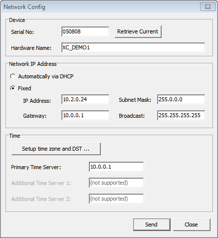
In the Network Config window, you can change the current IP configuration of a certain device.
Serial No
The device the network settings of which are shown, is always represented by its Serial No. This serial number is unambiguous and valid for only one controller. The field is used to read out settings of devices that are located in a different network segment. Find more details on this in the following section “Requested device is NOT available in the list (b)”.
Hardware Name
Every Series 52 system can be assigned a Hardware Name for better identification of the system. This name helps to identify the device in the network. You can choose any name, it can be up to 30 digits long but may not contain spaces. Special characters that are not allowed, can not be entered. In the Maintenance Window only the first 10 digits of the hardware name are shown.
Automatically via DHCP
If a DHCP server is located in the network that manages the IP configuration of the selected device, select the option Automatically via DHCP.
Fixed - Fixed IP setting
If you have no access to a DHCP server or want to adjust the IP configuration manually, first select Fixed and then enter the appropriate values (IP-address, Subnet Mask, Gateway, Broadcast) into the appropriate boxes.
Tip
As factory default DHD devices will be delivered with IP basic settings based on their MAC address. See IP basic settings for more information.
Important
In case of question concerning the parameter settings, ask your IT department or your system administrator.
Time Server
Series 52 systems have an internal system time that can be synchronised using a NTP Time Server. To do this, enter the IP address of your NTP Time Server in the Time Server box.
Depending on your chosen time server you may need to enter some further settings. Click Setup time zone and DST to be able to enter a general time zone offset and if necessary the settings for the daylight saving time.
Tip
A standard Windows PC can be used as a NTP time server, see Configure Windows as a NTP time server
With 52/XC2/XD2/XS2 cores you also can define two additional Time Servers. If the primary time server is not reachable, the core will use Additional Time Server 1. If Additional Time Server 1 is not reachable, the core will use Additional Time Server 2.
Requested device is NOT available in the List (b)
You need to add the device manually to your list by using the DHDCS - see Add device.
After adding the device manually to the DHDCS it might be possible, that the Network Config window opens with all boxes empty. Click Retrieve Current.
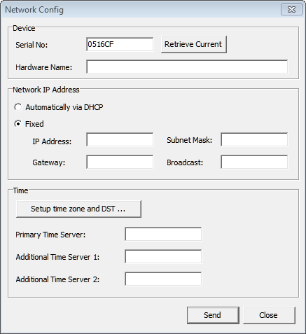
This way the device will transfer the current IP settings. These are then shown in the Network Config window and can be changed there.
Changing the data is carried out exactly as described in Requested device is available in the List (a). Changed data are finally transferred to the device by clicking Send.
Nevertheless, if the device is not reacting, communication could be blocked by certain IP settings. In this case it is recommended to adjust the IP settings of the PC to the ones of the device. To do this, temporarily change the IP address of the PC to the one valid for the device. (see IP basic PC settings)
There is no communication possible with the device
If, despite all efforts, the device is not reacting although there is a physical connection to your network, the communication might be blocked due to the current security settings in the network. In this case, check which measures for a higher network security may be dropped (e.g., firewalls, router, managed switches, …).
For solving the connection problems, contact the responsible IT department and check which of the measures described in the network specification have to be done to establish a communication between PC and DHD system.
Enter License
See Licensing Pages for more Information.
Using this command, you can enter the license codes. There are license codes for the firmware, for software operation snd for feature upgrades, like the Enhanced DSP Processing license.
Note
An invalid firmware license code allows unrestricted operation of a device for 600 operating hours, this corresponds to 25 days non-stop operation. After that, the message License invalid is shown in the module display and TFT displays. Apart from this message, the mixer operation is still unrestricted (except the enhanced DSP functions). After 800 hours of operation without a valid firmware license, the system is interrupted by a random reset approx. once per hour.
Generally, only one license code is necessary for operating one DHD system. Each system has its own license code based on the serial number of the device. You find the serial number under Serial Number Device in the firmware section after selecting a device.
Important
You can also get the license for a Communication Controller module. When exchanging this module, you might need a new firmware license code that you can request from DHD.
In most cases, DHD products are delivered with a temporary license code (valid until…). As soon as the system has become the property of the customer, DHD sends the permanent license code by e-mail. When you have received the license code, copy it by pressing Ctrl+C. Then select the desired device in the device list and select Enter License. Then, insert the code into the box by pressing Ctrl+V and confirm by clicking OK. The code is transferred to the device.
Check whether the license code was accepted. To do this, in the main menu, click License Information. If you read Firmware License: unlimited valid or for temporary licenses valid until with a new date, the transfer was successful.
An invalid license code will be ignored!
System Status
Save To File
In the Device menu, select System Status - Save to File, to save the currently read out status of the device. A file named System_Status_<Project ID>_<Hardware Name>_<Date>_<Time>.tgz is created.
If you want to read out the saved content, you first have to unzip it using a ZIP-decompressor. The result is a file with the same name but the extension .tar. Now, open this file using a RAR-decompressor. Finally, some files with the extension .xml emerge as well as some files necessary to show the XML files. You can view the XML files in a browser (e.g., the Microsoft Internet Explorer). For this, open index.xml. The view is the same as if you had selected the device in the device list. Then, you can view the other pages like in the Maintenance software.
Send By Mail
This function creates in a first step the same zipped file like the command Save to File.
Then, you instantly can send this file per e-mail to DHD support. For this, it is necessary to have an E-Mail Client installed on the PC and to set up an user account. In this case, a new mail window is opened automatically and the files created are attached. Only click Send and the e-mail is transferred to the DHD support team.
Download
If you created a System Status - file using Save To File or Send By Mail and don't want (or don't need) to create a new file, e.g. if you have high Load on your core, you can download the already created file here.
Restore Snapshots
With this function it is possible to transfer one or more mixer and channel snapshots from the PC to the console. (Use the function Save to File to save all mixer and channel snapshots of a device.)
Note
A firmware reset is required if mixer or channel snapshot names are also being restored.
Otherwise the restored snapshot names will not be shown in snapshot menus.
Alternatively you can use DHD Operation Manager to do your snapshot management.
Mixer 1 to 4
In the TB8 software, you can create several virtual mixers for a mixing device. Select a mixer that you want to save in the snapshot. If you did not create virtual mixers, save the snapshots in Mixer 1.
Save Snapshot 0
This command copies the current content of the parameter RAM of a mixing device to the Mixer Snapshot 0 storage area in the flash storage of the Communication Controller. This way, the settings are kept also after switching off the device and can be used as default setup after a reset. Snapshot 0 can also be loaded via the console like all other snapshots.
Note
The Default Snapshot 0 can only be saved using this command. There is no option to do this at the console!
First you have to select the desired device to trigger the command. After that, a security confirmation message Save current Parameter settings? is shown. After confirming with Yes the settings are copied.
Important
It is vital to choose the command Save Snapshot 0 after every setting into operation or after changing the configuration of the fader channels of a mixing device! Only this way, the system can restart using parameters that make sense after a reset, especially for the settings of Analog Gain, Phantom power, Fader assignment and Bus assignment!
Clear Parameter Memory
This function sets all DSP parameters of all channels to the default values.
Important
Resetting the parameters influences the audio processing of all channels. Make sure that it does not adversely affect important signals.
Firmware Reset
Select Firmware Reset to restart the firmware of the selected device.
You find the Firmware Reset command also in the contextual menu by right-clicking on a device in the device list.
Warning
A firmware reset temporarily interrupts the audio processing of the system. Make a firmware reset only if you are sure that it does not influence important signals.
System Reboot
Select System Reboot to restart the boot loader of the selected device.
You find the System Reboot command also in the contextual menu by right-clicking on a device in the device list.
Warning
A system reboot temporarily interrupts the audio processing of the system. Make a system reboot only if you are sure that it does not influence important signals.
Factory Test
This function can be used to check every single element of the fader and control modules of a mixing console.
Before a device is shipped, the functionality of all elements is tested by DHD. If you think that your console could have a hardware problem (e.g., a key is not working), you can clarify this with the aid of this function.
Before you use this option, you should transfer an empty configuration to the device. This makes the results more clear, because there will be no overlapping with the configured functions. Therefore, add a new device to your Toolbox5 project and transfer this empty configuration into the device.
Testable with this function are faders, keys, encoders, potentiometers, OLED displays and LEDs. The functionality of the TFT displays can not be checked with the factory test.
Keys
By pressing a key it will light up for approx. 3 to 5 seconds. Independently if you press the same or several keys after each other, the colour of the light will change automatically depending on possible states of the key (e.g., yellow-red-green, yellow-red-yellow or green-red-green). Additionally, pressing the keys of fader modules sets the fader values to defined positions (approx. +10 dB, -6 dB, -25 dB and -oo). Of course the fader itself will only move if it is a motor fader.
Faders
The current fader position is shown in the OLED display of this fader module as a digital value (typical values: min.=0005, max.=4093).
The modules 52-4240 and 52-4241 have six LEDs next to the fader (PGM 1/2, AUX 1-4). In the factory test mode, these LEDs also represent the fader value, but not that exactly as it is done in the OLED displays. The LEDs are standing for several bits (PGM 1 = 2^6 = 64, PGM 2 = 128, AUX 1 = 256 and so on). The LEDs of the modules 52-4230 and 52-4231 do not represent a bit pattern, they are driven as a running light.
If the console is grounded correctly, you will see a T in the OLED display when touching the fader. Also moving the fader is recognized as a touch and will cause a T in the display.
Encoders
In the OLED displays next to the encoders a value between 00000 and 65535 is shown that can be increased and decreased using the encoder. On pressing the encoder, a key of the same module lights up (pressing several times changes the colour).
Potentiometers
In the OLED displays next to the potentiometers a value between 0001 and 4093 is shown that can be increased and decreased using the potentiometer.