I/O Settings
On the I/O Settings page, you can configure different options for each input and output. Not all options are available for any input or output.
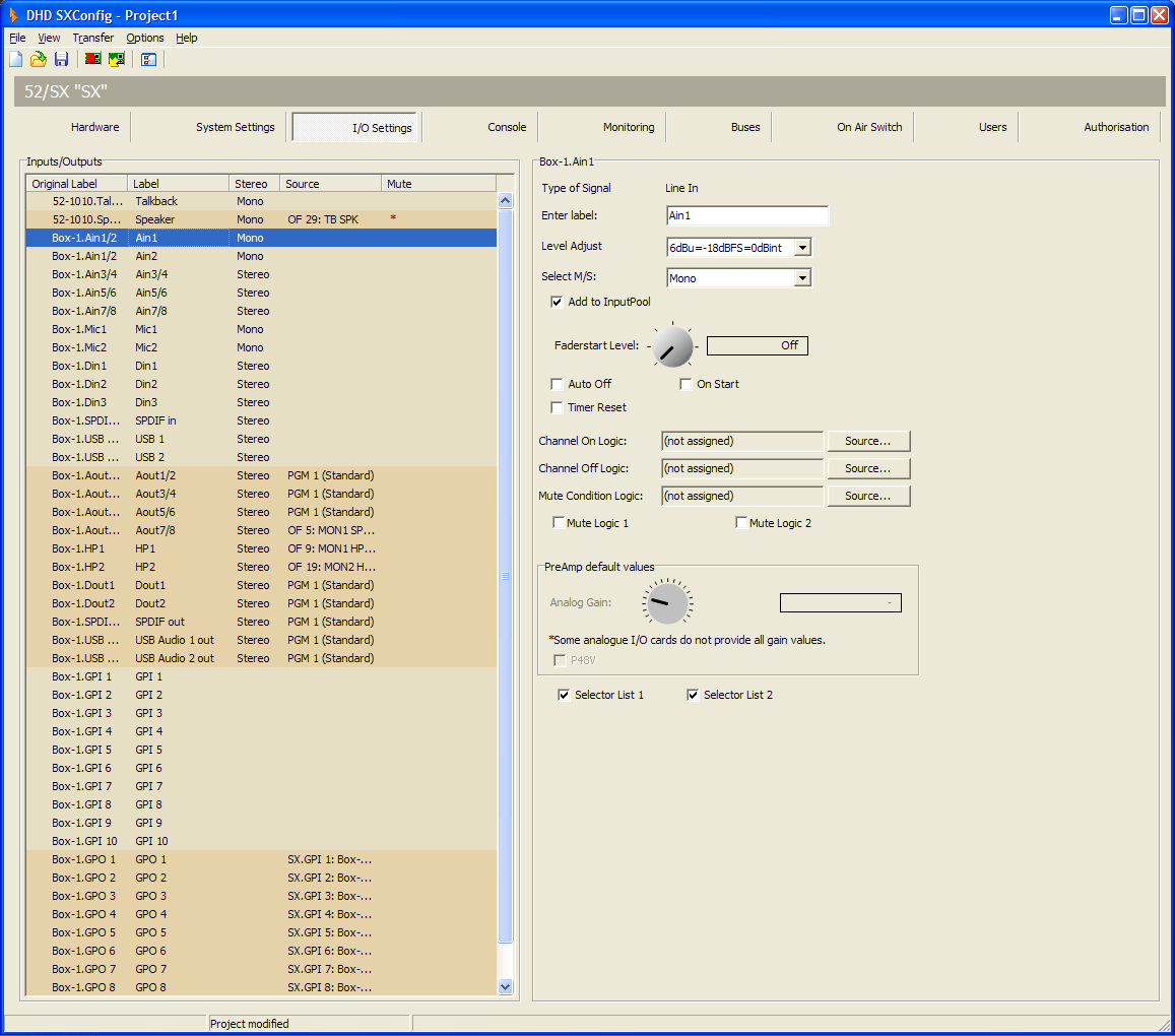
SXConfig Software - I/O Settings
In the following tables you can find the descriptions for these options.
Tip
For more information on internal and external leveling, see Toolbox 5 Documentation / Headroom Settings
Inputs/Outputs area
| option | description |
|---|---|
| Original Label | This column shows the internal label which is generated in that scheme: <module type→.<port label> |
| Label | Individual Label, double-click on the label and change the current name. |
| Stereo | Indicates if the signal is mono or stereo. |
| Source | Shows the assigned audio/logic source for input and output. |
| Mute | Shows, that a Mute Logic is assigned to an output. |
IOModule-X.<port> - Audio Inputs area
| option | description |
|---|---|
| Type of Signal | Shows the general signal type of the port. |
| Enter Label | Enter a distinctive name for the selected input. |
| Level Adjust | Choose the headroom for each input from the corresponding drop-down menu. The shown values always refer to the devices internal default level of 0 dBint. |
| Select M/S | Select, if the signal is mono or stereo. |
| Sample Rate Converter | Select from the drop down menu, if the sample rate converter is activated (On) or deactivated (Off) for this input. |
| Add to Input Pool | Select this check box to make this signal available for a channel on the console |
| Fader Start Level | Select a level, which sets the fader start logic to on. |
| Auto Off | By closing the fader, the channel is automatically switched OFF (ON key is deactivated). |
| On Start | The faderstart is only activated and deactivated by pushing the On/Off key, not by moving the fader. |
| Timer Reset | If this check box is selected, opening this fader will reset and start the Auto timer of the stopwatch. |
| Channel On Logic | Select a Logic Function from the Logic Sources window, which sets the channel to ON. You can choose, for example a GPI to open a channel. |
| Channel Off Logic | Select a Logic Function from the Logic Sources window, which sets the channel to OFF. You can choose, for example a GPI to close a channel. |
| Mute Condition Logic | Click Source to select a Logic source, that mutes the input, if the logic source becomes true. |
| Mute Logic 1,2 | Here, you can define which mute logics are enabled when opening a fader. Mostly, this assignment is used to mute speakers when opening microphone channels. You can control up to two mute logics. To do this, select the corresponding check boxes. To assign a mute logic to an output select the mute logic check box at a selected output on this tab. |
| Selector List 1 | Select this check box to add this audio source to source list 1. This Source will be available in the monitor source list, which is assigned to the Selector key on 52-1010 central module. |
| Selector List 2 | Select this check box to add this audio source to source list 2. This Source will be available for monitoring in the Monitor 2 list, which is available in the Selector view of the TFT/Touch Display. |
IOModule-X.<port> - Audio Outputs area
| option | description |
|---|---|
| Type of Signal | Shows the general signal type of the port. |
| Enter Label | Enter a distinctive name for the selected output. |
| Headroom | Choose the headroom for each output from the corresponding drop-down menu. The shown values always refer to the devices internal default level of 0 dBint. |
| Select M/S | Chose, if the signal is mono or stereo. |
| Sample Rate Converter | Select from the drop down menu, if the sample rate converter is activated (On) or deactivated (Off) for this output. |
| Dithering | If you connect devices with a lower resolution of the digital signals to a DHD device, here you can define how the internal audio signal is to be dithered before leaving the digital output. With this function, the quality of the output signal can be improved. You can select 16 bit, 20 bit, Off (no dithering, preset value). |
| Digital Out Mode | This option can adopt the values Pro (default value) or Consumer. |
| Source | You can assign an audio signal to a mono output. Click the Source button, the Audio sources window opens. Select an audio source, and click Assign. |
| Left Source | You can assign an audio signal to the left channel of the selected output. Click the Source button, the Audio sources window opens. Select an audio source, and click Assign. |
| Right Source | You can assign an audio signal to the right channel of the selected output. Click the Source button, the Audio sources window opens. Select an audio source, and click Assign. |
| Direct ACI | Select this check box to enable volume control for the headphones via a potentiometer which is connected to an ACI. This option is only available for headphone outputs. The ACI on D-sub port 1 is assigned to headphone 1 (HP1) and the ACI on D-sub port 2 is assigned to headphone 2 (HP2). |
| Mute Logic 1 | Select this check box to mute this output, if a fader with one of the inputs with selected Mute Logic 1 check box is opened. |
| Mute Logic 2 | Select this check box to mute this output, if a fader with one of the inputs with selected Mute Logic 2 check box is opened. |
Important
When switching Digital Out Mode between Pro or Consumer, following values are changed:
| Mode | Pro | Consumer |
|---|---|---|
| Terminator | 110 Ohm | 75 Ohm |
| Output Voltage | 5V | 0.5V |
| Data Stream | Professional Bit Set | Consumer Bit Set |
IOModule-X.<port> - General Purpose Inputs (GPI) area
| option | description |
|---|---|
| Type of Signal | Shows the general signal type of the port. |
| Enter Label | Enter a distinctive name for the selected input. |
IOModule-X.<port> - General Purpose Inputs (GPO) area
| option | description |
|---|---|
| Type of Signal | Shows the general signal type of the port. |
| Enter Label | Enter a distinctive name for the selected input. |
| Select Source | You can assign a logic sources to the selected GPO. Click the Source button, the Logic sources window opens. Select a logic source, and click Assign. |