Level Detection
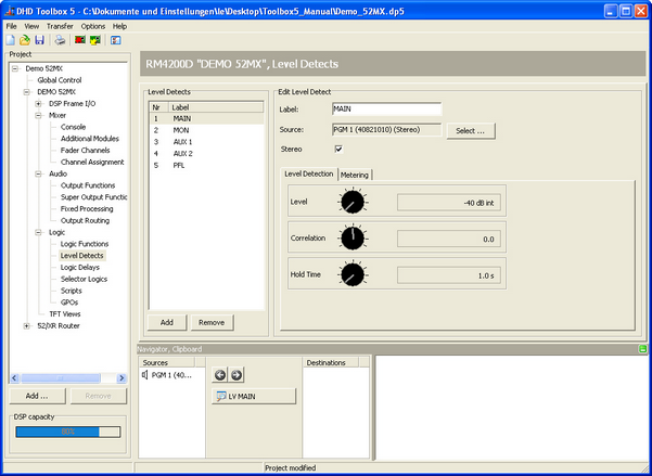
With the logic system of the mixing device you can monitor level and correlation of up to 24 audio signals at the same time. To configure these level detects, in the project tree, select <Device>/Logic/Level Detects.
Level detectors are configured accordingly to control logic functions that are activated if the level of the monitored audio signal exceeds a set threshold. These logic functions are available in the Logic Sources window under Level Detect/LV <serial number>: <Name> or Correlation Detect/LC <serial number>: <Name>. For each entry in the Level Detects list, in the Logic Sources window one entry each is inserted in Level Detect and Correlation Detect section.
You can output the state of the logic functions for example via a GPO or have it shown with an LED of an user defined key on the console.
To insert a new level and correlation detector to the Level Detects list, click Add. To remove a selected entry from the list, click Remove. Both functions are also available by right-click in the list.
To configure a level detector, follow these steps:
- In the
Level Detectslist, select the level detect which you want to configure. - In the Edit Level Detect area, type an appropriate name in the
Labelbox. This label may be up to 10 digits long. - To assign an audio source, click select. The
Audio Sourceswindow opens. - In the
Audio Sourceswindow, select the audio signal that you want to monitor and clickAssign. Alternatively you can double-click on the desired audio source or drag it to theSourcebox. - If the
Stereocheck box is selected, additionally, the following channel is also used for monitoring. In most cases, this is the right channel of a stereo signal.
Settings on the Level Detection tab:
- At the
Levelpotentiometer define the desired threshold value. You can select a value between -40 dBint and +10 dBint in steps of 1 dB. - Independent from the set threshold value at the
Levelpotentiometer, you can set a value between -1.0 and 1.0 for the correlation monitoring at theCorrelationpotentiometer. If this value is exceeded, the logic functionCorrelation Detect/LC <serial number>: <Name>is activated. - At the
Hold Timepotentiometer you can define how long the logic functionsLevel Detect/LV <serial number>: <Name>andCorrelation Detect/LC <serial number>: <Name>remain active after the threshold is exceeded. You can set the hold time between 0.1 ms and 100 ms.
Note
The logic function Correlation Detect is intended for metering. The correlation detection only works for signal levels greater than -30 dBint. That is why DHD does not recommend to use this function as a logic source.
Settings on the Metering tab:
- With the
Attackpotentiometer you can define how quickly the PPM display in the TFT displays react. You can set this attack time between 0 ms and 250 ms. - With the
Releasepotentiometer you can set the release time of the PPM display in the TFT displays. You can set this time between 0.1 s and 2.5 s.
Tip
To emulate an analog level meter with an integration time of 10 ms concerning to IEC 268-10 (PPM, Type I) and DIN 45406 respectively, please use the following values:
• Attack = 2 ms
• Release = 0.7 s
Please use the following values to emulate a digital level meter:
• Attack = 0 ms (or 1 ms, if integration time is required)
• Release = 0.7 s
To adjust the potentiometers, click on the desired potentiometer. Hold the mouse button and move the cursor to the left or the right to change the value. Alternatively, click on the desired potentiometer and change the value using the following keys:
| cursor keys | level potentiometer | correlation potentiometer | hold time potentiometer | attack potentiometer | release potentiometer |
|---|---|---|---|---|---|
| right arrow key or up arrow key | steps of +1 dB | steps of +0.1 | steps of +0.1 s | steps of +0.1 ms | steps of +0.01 s |
| left arrow key or down arrow key | steps of -1 dB | steps of -0.1 | steps of -0.1 s | steps of -0.1 ms | steps of -0.01 s |
| Pos 1 | -40 dBint | -1.0 | 0.1 ms | 0 ms | 0.1 s |
| End | +10 dBint | +1.0 | 100 ms | 250 ms | 2.5 s |
| Page up | steps of 5% (+2 dB) | steps of 5% (+0.1) | steps of 5% (+4.9 s) | steps of 5% (+12 ms) | steps of 5% (+12 ms) |
| Page down | steps of 5% ( -2 dB) | steps of 5% (-0.1) | steps of 5% (-4.9 s) | steps of 5% (-12 ms) | steps of 5% (-12 ms) |
The level detects can also be used inverted as logic source in logic functions or GPOs to detect undershootings. By an AND concatenation in a logic function with the logic source Pulse 1 (or 2, 3) also flashing functions when exceeding or falling below a certain level can be configured.
The correlation detects can be used as logic source to recognise whether both parts of a stereo signal are similar (1) or at least relative (0.1-0.9). In the negative range, the logic source shows faulty stereo signals (-1 to 0) that can not be used for mono.
R128 Loudness Metering
The loudness metering is available for all Series 52 mixing consoles when using 52/XS Cores 52-1801/52-1804, 52/XC Cores 52-740x or 52/XD Cores 52-744x.
Important
- The R128 loudness metering is not (and will not be) available for the RM4200D DSP Frame or 52/XR MADI Router!
- Toolbox5 Version 7.1.4 or higher is required to use R128 loudness metering function.
- The Hardware needs the license 52-8581 Enhanced DSP Processing (necessary for all Cores).
- 52/XS Core hardware additionally requires the license 52-1950 XS Core extended feature upgrade to be able to configure the function and the TFT views.
The loudness metering in DHD consoles follows the EBU R128 standard.
To configure the R128 loudness meter in the Toolbox5 software, follow these steps:
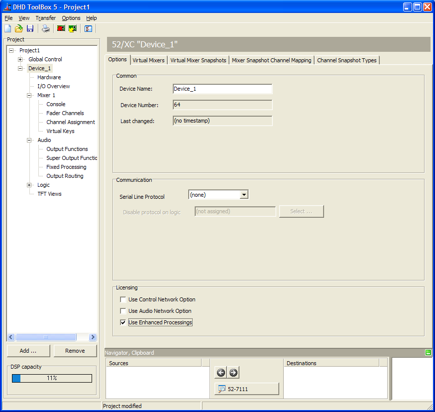
1. In the project area, select your <Device>. On the Options tab, in the Licensing area, select the Use Enhanced Processings check box.
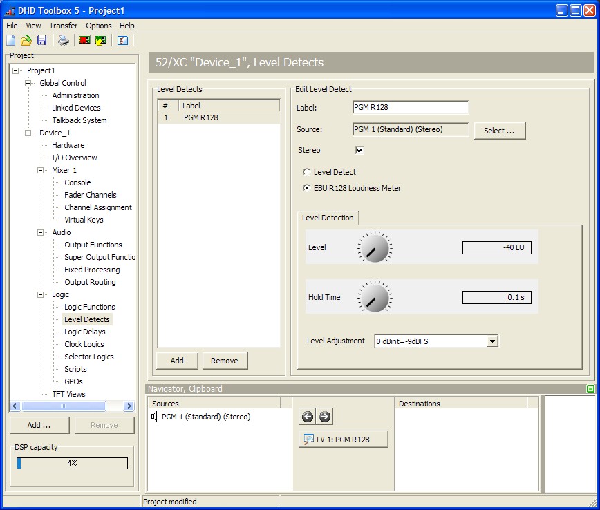
2. In the project area, select <Device>/Logic/Level Detects. Add a new level detect and in the Edit Level Detect area select EBU R128 Loudness Meter. Assign for example the PGM Bus as Source for the R128 Loudness Meter.
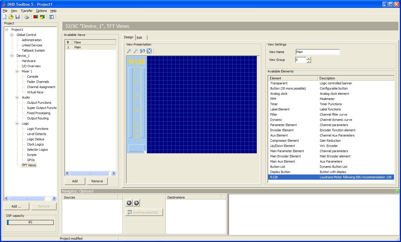
3. In the project area, select <Device>/TFT Views. Select an existing TFT Master view or add a new one. On the Design tab, drag a R128 element from the Available Elements list to the View Presentation area.
- R128 element contains only the bar (incl. peak display and short value arrow)
- short value graphically shown as a small triangle on the left side
- true peak display on top of the meter bar (oversampled x4, -1dBFS)
- if required, Momentary, Short, Integrated, Loudnes Range values (M, S, I, LRA) can be added as extra Label Elements - size, label and colour can be customized
- start, stop and reset are available as key function, gating (triggered by external sources) can be realised via virtual keys.
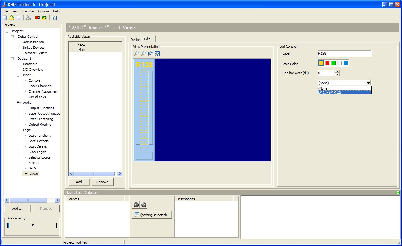
4. On the Edit tab, select the Data Source for the R128 element.
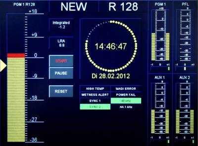
The final TFT view can be configured like this: