Surround Configuration | Up to TB5 v7.3
Note
5.1 mixing functionality is available for DHD 52/MX and 52/XR devices with firmware version 6.4.4 or higher and a suitable TB5 version.
Note
This function is redesigned in TB5 v7.4. See This Page.
Signal Flow of 5.1 Surround and Stereo Mixing Busses
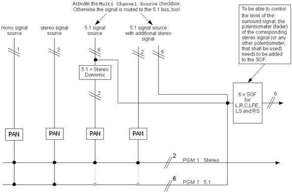
The following flow chart shows the signal flow of mono, stereo and surround signals connected to stereo and surround busses.
Mixing Mono and Stereo Signals to 5.1 Busses
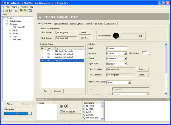
First of all, it is necessary to create a 5.1 mixing bus. Therefore, in the project tree, select <Device>/<Mixer>. Create a new PGM bus and select Surround 5.1 in the Format list. The Bus Number needs to be incremented according to the number of existing PGM busses (in this example the PGM busses 1 and 2 are stereo; PGM bus 3 is 5.1). Do not start with bus number one again, because the 5.1 bus is added to the existing PGM busses.
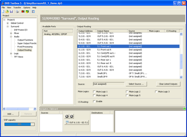
The output routing works in the same way like it does for mono and stereo busses. In the project tree, select <Device>/Audio/Output Routing. Choose six unused outputs you want to use as surround channels. Click Select Source. In the Audio Sources window, select Mixing Functions and drag every 5.1 channel to the desired output in the Output Routing list.
Note
Surround panning and further 5.1 channel options are explained in the section Miscellaneous Surround Functions.
Working with 5.1 Input Signals
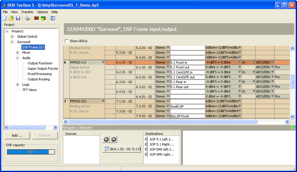
Proceed as follows, if you want to feed your DHD system with 5.1 signals. In the project tree, select <Device>/DSP Frame I/O, find the surround inputs and enter appropriate names.
Afterwards, in the project tree, select <Device>/Audio/Super Output Functions. Add six super output functions (SOF) in the left column and name them similar to the inputs. Each SOF must fit to one of the six surround channels (5.1 front left, 5.1 front right, 5.1 center and so on).
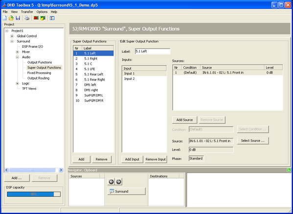
Select one of the surround super output functions (e.g., 5.1 Left), click Select Source and choose the corresponding audio input. Repeat this for each of the 6 SOFs. If more inputs are added to each SOF, further 5.1 sources can be added in the same way. These sources are mixed to the output of the SOF. In the <Device>/Audio/Output Routing section you can assign every SOF to a desired physical output (see Mixing Mono and Stereo Signals to 5.1 Busses).
You may want to have a fader for every 5.1 signal. Therefore, you can use every potentiometer or fader of your system. For additional options, double-click a source in a SOF to open the Audio Sources window. Here, you can choose the desired potentiometer and assign an amplification/attenuation value for every input source. If you use a stereo downmix for simultaneous stereo broadcasting, it is possible to use one fader to control the level of both signals (5.1 and stereo) together.
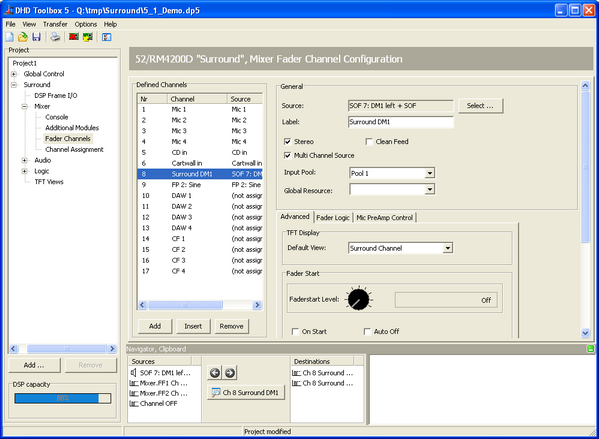
If you want to have a separate fader for a 5.1 source, you have to create it in the following way. In the project tree, select <Device>/<Mixer>/Fader Channels and create a new fader channel. Enter an appropriate name for the fader channel and assign it to a physical fader (Channel Assignment). For every fader a virtual potentiometer is created automatically. You can find these potentiometers on the Potentiometer tab in the <Device>/Audio section. Assign the virtual potentiometer of the desired fader to the six surround channels in the respective SOFs.
Important
If you use the fader of a stereo downmix fader channel to control a 5.1 source in the background (simultaneously to the stereo signal), it is important to define this stereo channel as multi channel source. This can be done by selecting the Multi Channel Source check box for this fader channel.
That means, if Multi Channel Source is selected, the signals of this fader channel are not routed to the surround bus. Otherwise it would be possible to overlay a downmix and the original 5.1 signal on the surround bus (see picture Signal flow of mono, stereo and surround signals).
Working with 5.1, Stereo and Mono Sources
If you want to add stereo and mono signals to 5.1 sources, the configuration process is a mixture of the two aforementioned possibilities. At first, follow the instructions of the section Working with 5.1 Input Signals. Afterwards, create a surround program bus like described in the section Mixing Mono and Stereo Signals to 5.1 Busses. This surround bus needs to be added to the six SOFs (see Working with 5.1 Input Signals) as an additional input. This way, the surround program bus is mixed with the other surround input signals in these super output functions.
How to Create a 5.1 to Stereo Downmix
In a broadcasting environment, surround programs are mostly produced parallel to compatible stereo versions of the same content. Therefore, or for simple monitoring applications it is useful to create a 5.1 to stereo downmix in the background.
The mix levels for each of the surround channels in the following descriptions are taken from the appropriate recommendations by the ITU (International Telecommunication Union). Other levels are possible and may dependent on your special needs.
Downmix | TB5 up to v7.3
Downmix a 5.1 Source to a Stereo Input
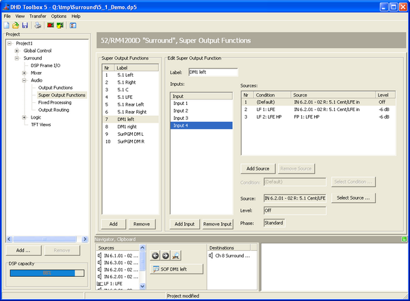
An input downmix makes it possible to use surround signals as input source for stereo fader channels. Create two additional super output functions (one for the left and one for the right signal of the stereo channel) and give them appropriate names. Select the SOF of the left channel and create four inputs. These inputs are mixed to the SOF output. Assign the sources to each input as well as the desired attenuation.
- Input 1: Front Left with no attenuation (Level =
0 dB) - Input 2: Rear Left with an attenuation of 3 dB (Level =
-3 dB) - Input 3: Center with an attenuation of 3 dB (Level =
-3 dB) - Input 4: LFE, set to
Off
Configure the right channel in the same way. The outputs of these two SOFs can be used as source for every fader channel to create a stereo mix.
If you want to switch between several mixing ratios, you need to add the same sources several times to every input of the downmix SOF. The difference is the desired level you have to define. Switching between the sources with different levels can be done by every available logic condition. Therefore, in the Edit Super Output Function area, select an audio source and click Select Condition. Do not forget to assign these conditions to the sources of the related SOF, too.
Downmix Surround PGM Bus to Stereo Output
For monitoring purposes, it is sometimes required to create a stereo downmix of the surround program bus signals. Therefore, you have to create two super output functions with 4 inputs like it is described in the section Downmix a 5.1 Source to a Stereo Input. The audio sources of the SOF inputs are the channels of the surround program bus. Select the input sources, click Select Source and choose the channels of the surround bus, located under mixing functions.

Downmix Surround to Mono
If a downmix from surround to mono is needed, this is done similar like it is described in the sections Downmix a 5.1 Source to a Stereo Input and Downmix Surround PGM Bus to Stereo Output. But of course, in this case only one super output function is needed. This SOF needs to have 6 inputs to include each of the six surround sources in the mono mix. The following mixing ratios for surround to mono downmixes are recommended by the ITU (International Telecommunication Union).
- Input 1: Front Left with an attenuation of 3 dB (Level =
-3 dB) - Input 2: Front Right with an attenuation of 3 dB (Level =
-3 dB) - Input 3: Center with no attenuation (Level =
0 dB) - Input 4: Rear Left with an attenuation of 6 dB (Level =
-6 dB) - Input 5: Rear Right with an attenuation of 6 dB (Level =
-6 dB) - Input 6: LFE, set to
Off
The output of this SOF can be used as a mono audio source.
LFE Channel Handling in Surround Downmixes
The ITU (International Telecommunication Union) does not recommend to add the LFE channel to surround downmixes in general, to protect smaller playback systems from damage or signal distortion caused by high level of low frequencies this systems can not deal with. If you want to include LFE channels to your downmix, it is reasonable to provide several, switchable mixing ratios.
This can be realised with the already created super output functions. Select an input for the LFE channel and create as many sources as mixing ratios shall be provided. Assign the LFE channel audio input to every source of the respective SOF input and define an amplification/attenuation value. The first source of the SOF input should be set to Off to be sure, that it is not added to the downmix by default. For the other sources you should set some useful level values. The different sources can be chosen by logic conditions. For example logic functions controlled by user defined buttons of a mixing console.
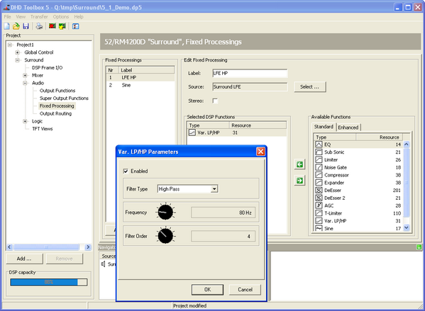
For protection purposes it is also possible to add a high pass filter to the LFE channel. To realise that, you can send the LFE signal to a fixed processing with a high pass filter and a desired cut-off-frequency, respectively. The output of this fixed processing can be used in the downmix.
Please see the section Downmix a 5.1 Source to a Stereo Input to find general information on creating super output functions.
Miscellaneous Surround Functions
The best way to handle surround functions is to use TFT displays and encoder elements. Therefore, three new encoder elements have been designed.
- 5.1 Pan/Bal - Enables you to pan between left, center and right.
- 5.1 Surround - Enables you to pan between front and rear.
- 5.1 Misc - Enables you to control further surround parameters.
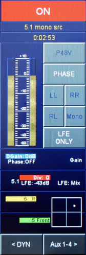
5.1 Misc parameters
LFE Send: Enables you to send signals to the LFE channel with a desired level. The level is settable between -oo and +15 dB. The LFE send is fixed located after the fader.
LFE Mix/only:
LFE Mixis the standard operating mode. The LFE send signal is used as the normal program signal.LFE onlymutes the channels FL, FR, C, LS, RS and the signal is only send to the LFE channel. The LFE effect level can be controlled by the fader. Please keep in mind, that the LFE send is an after fader function.
Divergency: Enables you to define whether the signal of the center speaker is only generated by the center signal (setDivergencyto 10) or as a phantom sound source created by the left and the right signal (setDivergencyto 0). Interim values can also be chosen.
In TFT views for 5.1 Pan/Bal and 5.1 surround panning it is useful to locate the surround panning encoder element directly underneath the Pan/Bal encoder element. If you combine these encoder elements, a quadratic matrix is shown wherein the position of the phantom sound source is visualised.
Note
If there is at least one surround bus configured in the system, the standard Pan/Bal encoder element is expanded by the surround panning options and the misc functions. This is especially useful, if there is less space left in the TFT fader view or if there are not enough encoders available, because you are able to control all surround panning options and misc functions with one encoder.

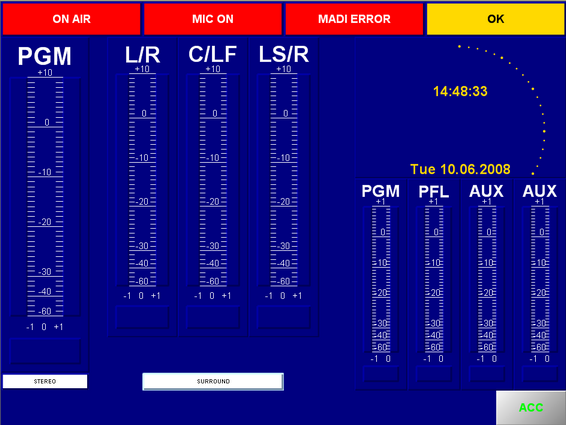
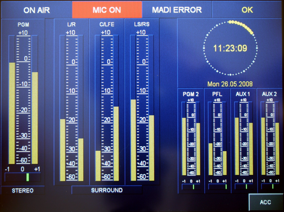
Surround Peak Meter (PPM)
To show surround signals you need to configure three stereo level detects and three PPMs. The sources of the level detects are L/R, C/LFE and LS/RS. Please notice, that the center and LFE signals are handled as a stereo pair internally. This way, the Center and LFE levels can be shown with one PPM. Thereby, the left signal is always center and the right signal is LFE.
It is possible to switch off the correlation meter of a PPM in the edit section after selecting a PPM. This is important to do for the stereo peak meter that shows the center/LFE signals, because in this case the shown values of the correlation meter are not useful.
Surround Monitoring
The following example explains a possibility how to monitor stereo and surround sources on a 5.1 monitoring system.
At first, it is necessary to choose some buttons for switching between the different sources. Select the key function user defined for these buttons and enter appropriate names (for example: PGM 5.1 PGM Stereo, PGM Downmix).
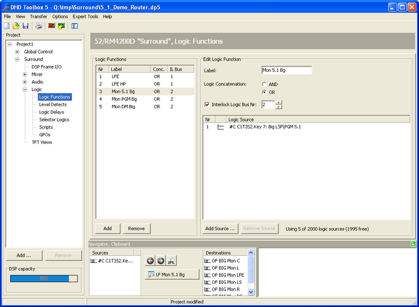
In the project tree, select <Device>/Logic/Logic Functions and create a logic function for each source you want to be able to choose. The sources of the logic functions are the corresponding user defined buttons. It is important to group these logic functions and to assign them to interlock logic busses, so that always only one of the sources can be activated. That means, an active source is switched of if another source is selected.
Moreover, it is necessary to define a potentiometer that is used to level the loudspeakers. Depending on the used hardware modules, a defined number of potentiometers is configured by the system automatically (potentiometers of hardware modules). If you want to use such a hardware potentiometer for leveling, you do not need to take care about the next paragraph.
If an encoder should be used for leveling you have to create a software potentiometer by yourself. Therefore, in the project tree, select the <Device>/Audio and select the Potentiometer tab. Add a software potentiometer, enter an appropriate name and assign it to the mixer wherein the potentiometer will be used. In the project tree, select <Device>/<Mixer>/Console, select the desired encoder on the console and choose Potentiometer in the Function box. A list with all available potentiometers shows up and you have to select the afore created software potentiometer.
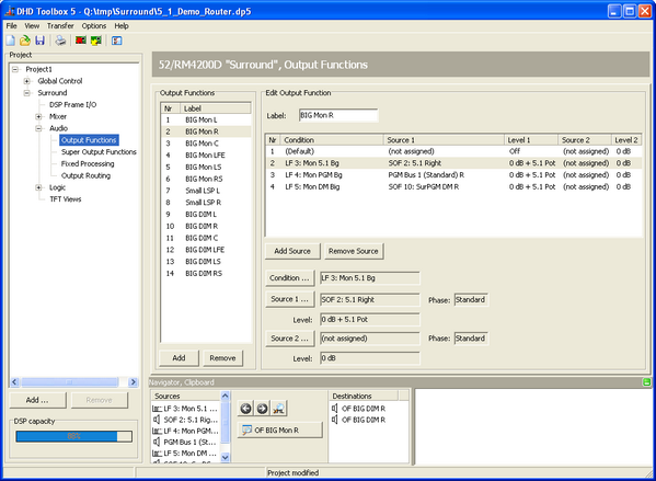
Output functions are required for each mono channel to handle the switching between the audio sources and to connect potentiometers to these sources. Accordingly, you have to create 6 output functions for a 5.1 signal. Do not assign any source to the first source of every output function and set the level to Off. This makes it possible, that no audio is routed if none of the sources is selected. The output functions 1 and 2 are defined for stereo signals as well as the left and the right channels of 5.1 sources. The output functions 3, 4, 5 and 6 are created to handle the center, LFE and rear channels of the 5.1 signal. For example, if you have one surround and two stereo sources, you have to create 3 additional sources in the output functions 1 and 2 as well as one additional source in the output functions 3, 4, 5 and 6.
Select the audio signals that belong to the sources of each output function. In the Audio sources window you have to select the afore created potentiometer which should control the level of the audio that passes the respective output function.
Afterwards, you have to choose the logic conditions for switching between these sources. To do this, use the afore created logic functions. By pressing the user defined buttons, the sources are switched in the corresponding output functions.
In the project tree, select <Device>/Audio/Output Routing. Connect the output functions with a physical output.
If you want to create a DIM function for a 5.1 monitoring system the most simple way is to send the 6 created output functions to 6 extra output functions where the DIM is realised. These 6 output functions need to be assigned to the physical outputs.
Another possible way to do switching in the output functions is to use selector logics. Therefore, you have to use a selector and the monitor bus function on the keys, you want to use for switching. Within the monitor bus function you can only select stereo sources, that should be switched. Choose the created selector as well as the left and the right channel of the 5.1 signal as Left and Right Source. Consequently, you can use a selector logic as logical source for switching the audio sources of the output functions. Therefore, you have to add a selector logic for every 5.1 channel. Choose the created selector as left and right source at the corresponding monitor bus key. By pressing these monitor bus buttons to choose the left and the right channel, the selector logic becomes true and with the concerning output functions you can switch to C, LFE, LS and RS.
Which of the two ways you should use depends on your configuration and for what you have a preference for.