Output Functions
To configure output functions, in the project tree, select <Device>/<Audio>/Output Functions.
Output functions are universally applicable DSP functions for switching, level changing, talkback and summation applications. Often, these are used directly before an audio signal output. This is where the name comes from: output function.
Every output function has two audio inputs, Source 1 and Source 2. These inputs are summed. You can influence them by two corresponding level values. The special thing about this is the following: Both, the sources of the input signals as well as their levels can be changed according to logic conditions. The output signal of an output function itself is available as an audio source on the TDM bus. Using this method, the most different applications can be realised.
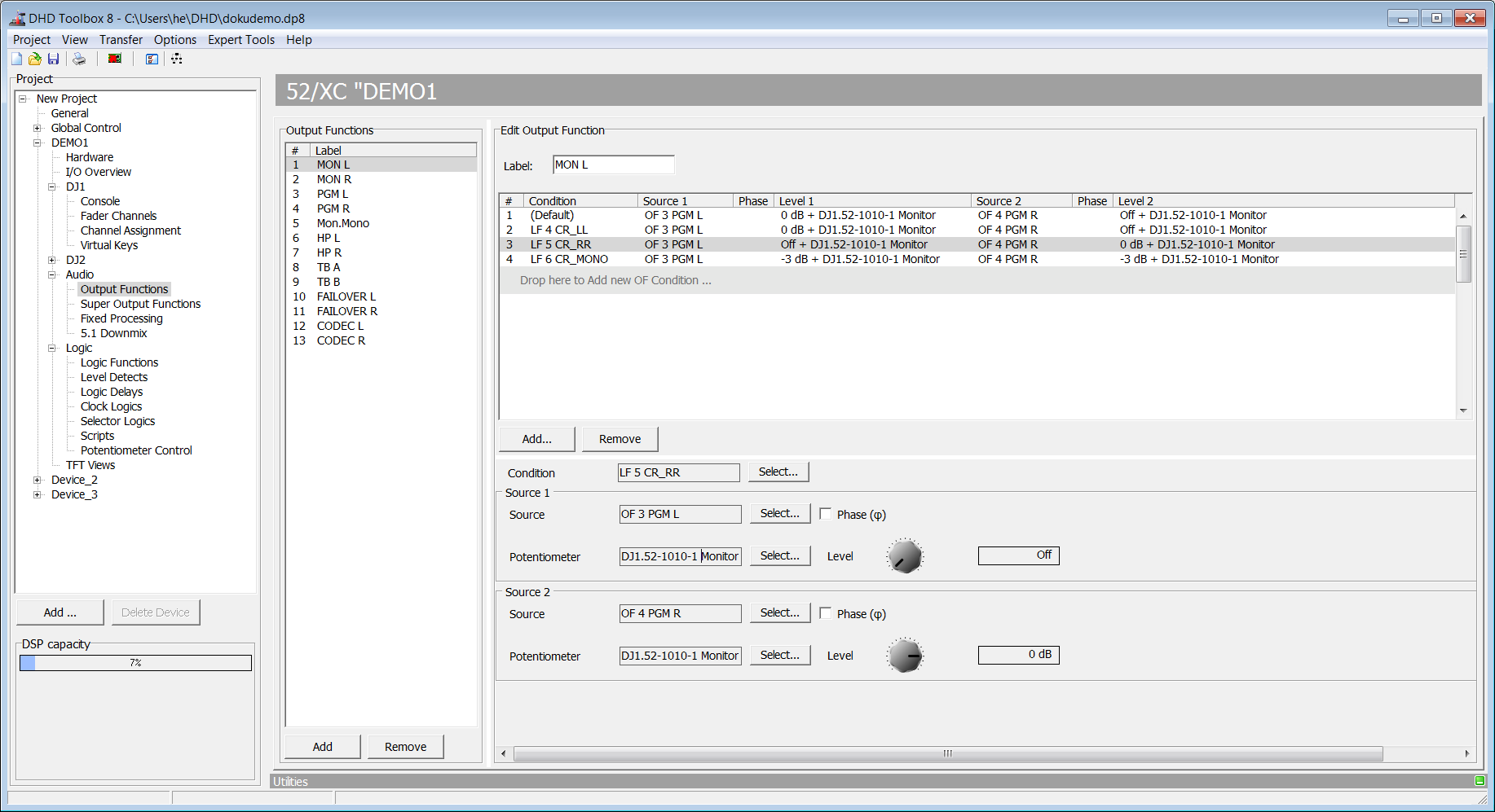
In the following figure, in the Edit Output Function area, you see an example of a configured output function:
The following signals can be used as input signals (Source 1 and Source 2) for output functions:
- Audio channels available on the internal TDM bus: inputs, delays, mixing functions (summing busses, groups, Aux busses), pre-fader signals (fader channels after input processing), clean feeds (n-1 busses), monitor functions, fixed processing, output functions, super output functions and talk outputs.
- You can set the levels (
Level) from -∞ (off), -100 dB up to +20 dB in steps of 1 dB. Further more, in addition to this fixed amplification value, the value of a potentiometer can be added and the phase position of the signal can be rotated by 180 degrees.
An output function can have the preset logic condition Default and up to 9 further logic conditions. Each of them is shown in the list in the Edit Output Function area. Each of them is shown as a row in that list. There you can assign other input signals and level values.
The logic condition Default is always in the top line and always active if none of the configured conditions below is active (logically true).
As logic conditions in the Condition column you can use all logic sources that are available in the Logic Sources window.
The priority of the logic conditions decreases from top to bottom. So a condition is only used if all conditions above it are inactive.
For the example in the figure, this means (viewed from bottom to top):
- If the logic source
CR_MONOis activated (CR_MONO key pressed), the fourth line is executed - the monitor pathsCR LandCR Rget to the output of the output functionCR LSP 1Las a mono summation with an attenuation of -3 dB.
- If at the same time with
CR_MONOthe logic conditionCR_RR(CR_RR key pressed) is active, the third line is executed - the monitor pathCR Rgets to the output of the output functionCR LSP 1L.
- If at the same time
CR_MONOand/orCR_RRand the logic conditionCR_LL(CR_LL key pressed) is active, the second line is executed - the monitor pathCR Lis routed to the output of the output functionCR LSP 1L.
- If none of the just mentioned logic conditions is active, the first line is executed - the monitor path
CR Lis routed to the output of the output functionCR LSP 1L.
If no other logic condition is programmed, always the first line Default is active.
Output functions are mono at the inputs and at the outputs. So for stereo signals, the left and the right channels have to be programmed separately!
To create a new output function, click Add. To delete a selected output function, click Remove. You can also right-click in the Output Function list to add or remove an output function.
Edit Output Functions
In the Edit Output Functions area, you can configure the output function which is selected in the Output Functions list.
To configure a created output function, follow these steps:
1. Enter a distinctive name for the output function in the Label box. Please note that the name should be comprehensive, because up to 120 output functions can be available per device.
2. Click Add to insert a new condition row. Now select the new condition row. Definiton fields (Condition, Source, Potentiometer and Level) are now displayed. For first row, condition is always default and therefore not clickable.
3. Click Condition to open the Logic Sources window.
4. In the Logic Sources window, select the desired logic source and click Assign. Alternatively, you can double-click on the logic source or drag it to the Condition column of the list. The first row of the list always contains the condition Default and can not be changed.
5. Assign the first audio sources to the selected condition row. To do this, click Select in the Source 1 Section to open the Audio Sources window.
6. In the Audio Sources window, select the desired audio source, click Assign.
7. Adjust the level using the potentiometer in the Source 1 Section. To change a level, click and hold the potentiometer button. If you move the cursor to the left or the right holding the mouse button, you can change the level. Alternatively, you can click on the button, hold the mouse button and change the value using the following keys:
| +1 dB steps | right arrow key or up arrow key |
| -1 dB steps | left arrow key or down arrow key |
| Off | Pos 1 |
| +20 dB | End |
| +5% steps (+6 dB) | Page up |
| -5% steps (-6 dB) | Page down |
7. To rotate the phase position of the selected audio source by 180 degrees, select the Phase Reverse check box.
8. Select a potentiometer, the level value of which becomes valid in addition to the level value already configured. For example, if you have set the level of the audio source to -3 dB, and the selected potentiometer is set to -15 dB, in total, the signal is attenuated to $-15 dB + (-3 dB) = -18 dB$. Select the desired potentiometer or select (none) if you do not want to use a potentiometer. (See also Potentiometer – Assigning Potentiometers)
9. To assign a second audio sources to the selected condition row, do the same in Source 2 section.
To configure the output functions, please note the following hints:
- To delete a complete condition row, select the desired row and click
Remove Source. - Select a condition row and right-click on it to access the options
Add Source,Condition,Source 1,Source 2andRemove Source. Further on, in the contextual menu, you can set the level ofSource 1andSource 2directly to0 dBorOff. - To configure the condition and the audio sources for the selected row directly, double-click the corresponding column in the list.
- Drag condition rows on a new position in the list to change its priority.
- You can re-ordered output functions by drag and drop
- Cut, Copy and Paste for Output Functions as well as for selected Conditions are available
- New Output Functions context menu option: “Add right Ch OF from this” - if the “left” channel was already programmed this function will automatically add the “right” channel Output Function.