Defining Logic Functions
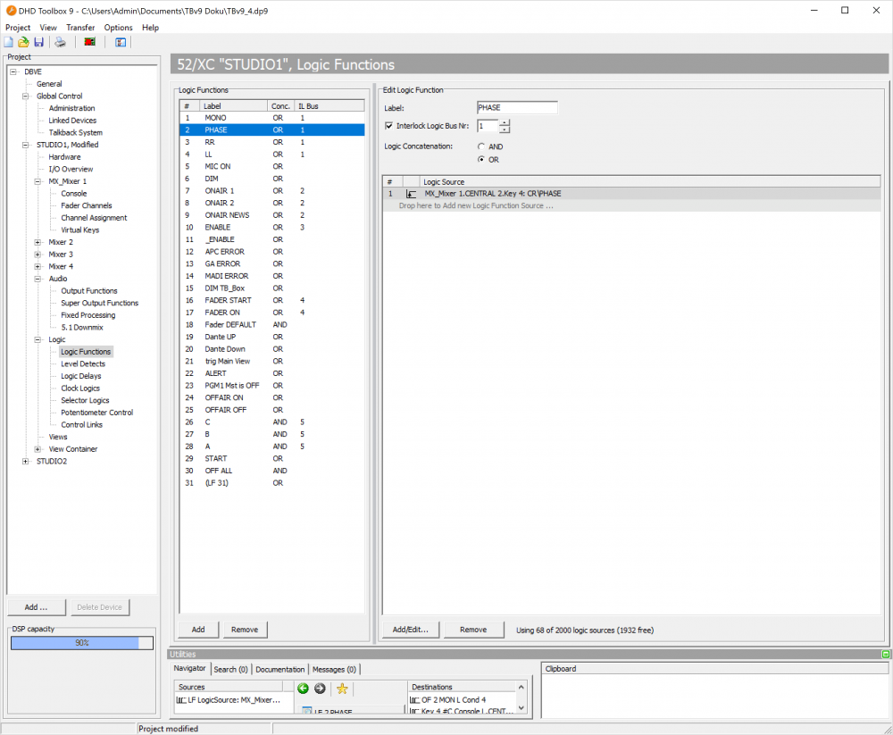
In the project tree, select <Device>/Logic/Logic Functions to create logic functions.
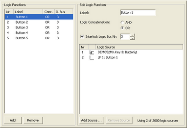
You can create up to 300 different logic functions per mixing device that can use a total of 2000 logic sources. For each logic function, you can link the logic sources using either OR or AND. In the logic sources list, for each functions the established links are shown. You can read the current state from the Conc. column. To form more complex Boolean operations, you can use already defined logic functions again as logic source for further logic functions.
Flip-Flop like functions can be created using Interlock Logic Busses. This is a special function which enables all logic functions on the same interlock logic bus to deactivate each other if one of the logic functions is activated. This way, you can create a set of key functions replacing each others because only one of the logic functions is active at any one time. Many other applications are possible. You can use up to 100 different interlock logic busses. If a logic function uses an interlock logic bus, its number is shown in the logic functions list in the IL Bus column. (See also Interlock Logic Bus)
The logic functions are processed every 20 ms in the communication controller. The sequence of the processing depends on the list order (top to bottom) that contains the logic functions in the configuration dialog.
To insert a new logic function into the Logic Functions list, click Add. To remove a selected entry from this list, click Remove. You can use both options by right-clicking inside the list. In the contextual menu, you can also define the edge type of the function which is explained later on.
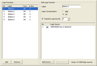
After you have selected the desired function in the Logic Functions list, you can configure it in the Edit Logic Function area. The following list describes a configuration example for a newly created logic function:
1. In the Label box, enter a descriptive name for the logic function. This label may be up to 10 characters long. Please note that this name may be important for the clarity of you configuration because a maximum of 300 logic functions is possible per device! The label is shown in the Logic Sources window behind the short description LF.
2. Click Add Source to open the Logic Sources window.
3. In the Logic Sources window, select the desired logic source.
4. Before assigning the logic source you should define its influence on the logic function. This characteristic is shown as a symbol for every logic source in the logic function. The following features can be defined:
| ON | | • The logic source works directly. |
| OFF | | • The logic source is inverted. |
| Pulse on activate | | • The rising edge activates the function. • Example: Key is pressed. Note Use only in relation with interlock logic bus! |
| Pulse on deactivate | | • The falling edge activates the function. • Example: Key is released. Note Use only in relation with interlock logic bus! |
Important
The options Pulse on activate and Pulse on deactivate may only be used in logic functions with activated interlock logic bus!
5. To assign the desired logic source with defined options to the logic function, in the Logic Sources window, click Assign. Alternatively you can double-click on the desired source or drag the logic source to the list in the Edit Logic Function area. If a logic source is selected in the list already, it is overwritten. The same happens if you drag a logic source into an already existing line of the list.
6. In the Edit Logic Function area, define whether the logic functions shall be AND or OR linked and linked to the Interlock Logic Bus. (Find details on this in the following sections of this manual.)
AND Concatenations
In an AND logic, all logic sources have to be true to make the logic function true. AND linked logic functions are indicated in the list by AND in the Conc. column of the Logic Functions list.
In the following example, the logic source Mixer Functions/Solo is linked with the logic source System Functions/Pulse 1 by an AND logic. The created logic function SOLOBLINK can be routed to the LED of an user defined key in a control module. This starts flashing if at least one solo key is pressed in a fader strip.
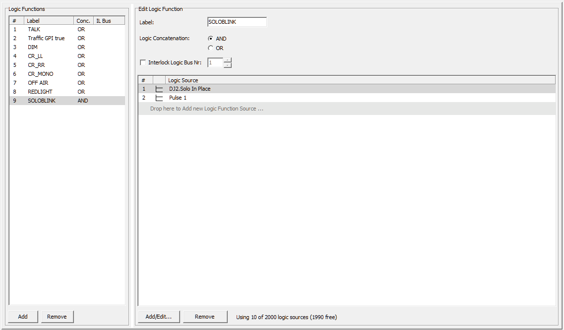
You can use the logic source Mixer Functions/Solo to toggle the speakers by an output function between the monitor bus and the solo bus. The flashing key indicates that the speakers are not routed to the monitor bus.
OR Concatenations
In an OR logic, at least one logic source has to be true for the logic function becomes true.
In the example of the figure below the logic sources Fader Start/Fader 1…4 A, Fader Start/Ch. 8…11 are OR linked with each other.
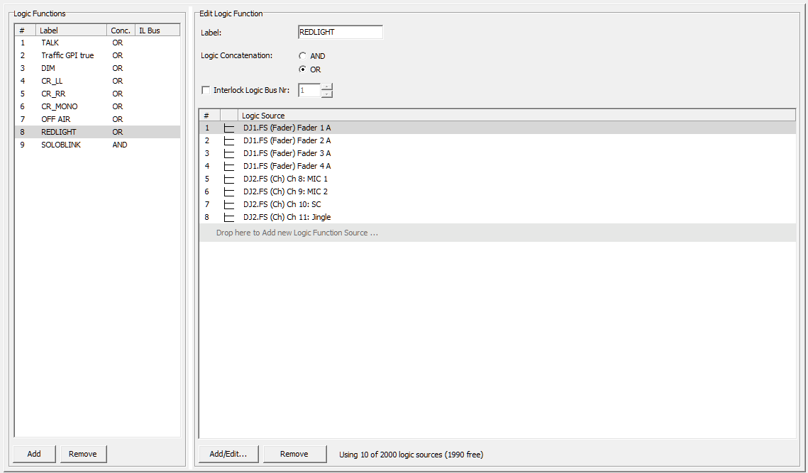
The logic function is enabled if the fader of at least at one of the four microphone channels is opened. This way, a red light could be switched on using a GPO.
Interlock Logic Bus
This function is used to link several logic functions so they can deactivate each other. All logic functions that must affect each other have to be routed to the same interlock logic bus.
You can use up to 100 different interlock logic busses at the same time, but any logic function can only be linked with one interlock logic bus. It is possible, that several of these logic functions can be used as inputs for further logic functions that use other interlock logic busses.
The function of an interlock logic bus can be described as follows:
1. If a logic function is linked to an interlock logic bus, at first it reacts normally. It becomes active if the concatenation of its logics sources (AND or OR) becomes true.
2. If a logic function with added interlock logic bus becomes active (true), all other logic functions that are routed to the same interlock logic bus Nr. become inactive. This way, enabling one logic function on the same interlock logic bus leads to the disabling of all other logic functions which are assigned to this interlock logic bus.
Because the logic functions in the device are processed one after the other, the state of a logic function can only be changed sensibly with enabled interlock logic bus via a rising or falling edge of the triggering logic source. If you use an already defined logic function as logic source, you can have the result output as an edge. For this, select the function in the Logic Sources window and select Pulse on activate or Pulse on deactivate. (See also Example 4)
Note
The shown number of the Interlock Logic Bus Nr. in the Edit Logic Function area is of no importance if the Interlock Logic Bus check box is not selected.
Examples:
The following examples illustrate how to use the interlock logic bus to solve real practical problems.
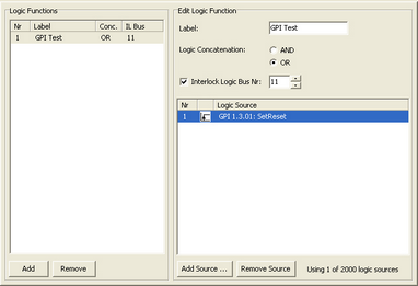
Example 1: Flip-Flop-Function
A logic function is set via the rising edge of a GPI and reset via the next rising edge (etc.).
Example 2: Key set, can be switched off
You can create an alternating set of keys by defining a logic function for every key. All these logic functions are linked by the same interlock logic bus. Each logic function has only the corresponding own key as logic source (with the feature Pulse on activate).
As soon as you press a key, its logic function becomes active; the previously active key is deactivated. When you press the currently active key again, it is switched off.
The logic functions controls the LEDs of the corresponding keys via the User Defined function.
Example 3: Set of keys that can not be switched off
This example corresponds to the set of keys of example 2, but with one difference: When pressing the currently active key, it is not switched off. All logic functions are disabled only after resetting the system.
Each of the logic functions has its corresponding own key as a logic source (Pulse on activate) AND, in addition, its inverted own logic function. This way, a function can only be executed if it is inactive.
The logic functions controls the LEDs of the corresponding keys via the function User Defined.
Example 4: Changing the status using two keys
The following complex example consists of a total of four logic functions. It shows how you can configure a set of keys consisting of two alternating keys. These keys behave as follows:
- There are two states only: Key 1 pressed (State A) and Key 2 pressed (State B); there is no state for A and B are both inactive.
If an already active key is pressed again, the state does not change.
The logic function Aaktiv is routed to the LED of the User Defined key A and the logic function Baktiv to the LED of the User Defined key B. Both logic functions can toggle, for example audio signals via output functions.
This arrangement requires an interlock logic bus in one of the logic functions. In the example it is Nr. 2 in the logic function Baktiv. The three other logic functions do not use an interlock logic bus.
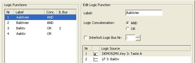
The logic function Aaktivier becomes active if state B is enabled and key A is pressed.

Baktivier becomes active if state B is inactive (e.g., state A is active) and key B is pressed.

Baktiv is assigned to interlock logic bus 2 and can change the state via Aaktivier or Baktivier. Which one of the OR linked logic sources sets or resets the function respectively, is defined by the logic function Aaktivier or Baktivier by the AND concatenation with the states B and A (=inverted B state).
Baktiv controls further on the LED source of the B key and the corresponding function.

Aaktiv is the inversion of the state Baktiv.
Aaktiv controls the LED source of key A or the corresponding function.