Clean Feed Structure
This section should give you an overview of the clean feed structure in Series 52 systems and the basic clean feed settings of the Toolbox5.
Besides the program busses and auxiliary busses, clean feeds can be created. These clean feeds could be used as return lines for telephones and OB vans. The signals of these clean feeds can also be used in a preliminary talk matrix. To create a n-1 return line for an incoming signal, you have to activate the Clean Feed check box of the desired fader channel (see Fader Channels/General Options/Clean Feed). This automatically creates a clean feed that can be found at Mixer/Mixing Functions. As it is known from PGM busses and AUX busses, you can set the properties of the clean feed busses in this area of the Toolbox5, too.
The following picture shows an example with two connected phones, each with an own n-1 return line. Depending on the selected mode, the signal of the clean feed or the signal of the preliminary talk matrix is sent on the return line. Additionally, at <Device>/<Mixer>, on the Mixing Functions tab talk sources can be defined. These sources are able to speak into the available busses. Two global sources for all busses can be configured. If you want to use more talk sources, this can be implemented with the aid of output functions.
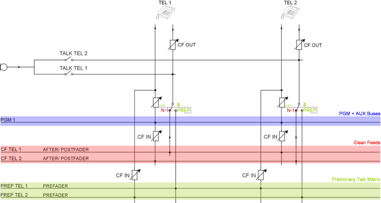
In the following the structure and the options of clean feeds are explained more detailed.
The clean feed is created from the program bus with the lowest number the corresponding input signal of the clean feed is currently assigned to.
Example: A telephone channel is connected to program bus 1, 2 and 3. Hence, its clean feed signal is created from program bus 1. If the same channel is only connected to program bus 2 and 3 and not to 1, its clean feed signal is created from program bus 2.
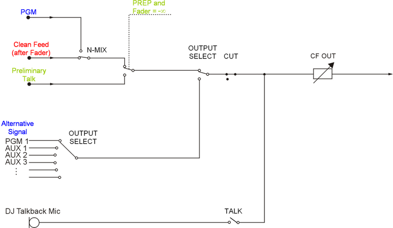
All functions of the clean feed are optional and need not to be configured if it is not necessary to provide these functions to the user:
N-Mix(see key function: CF N-Mix): Toggles between the clean feed signal (N-1) and the original program bus signal (MIX).PREP(see key function: Preparation CF): Switches between the clean feed signal and the signal of the preliminary talk matrix if the fader is closed.OUTPUT SELECT(see key function: Output Select CF, encoder function: CF Output Select): It is possible to feed an alternative signal in the return line instead of the clean feed signal. Use the key functionOutput Select CFto switch to the alternative signal. With the aid of an encoder with the functionCF Output Select, you can choose the desired signal. Therefore, you need to create an Output Selector Source List and to assign this list to the clean feed at <Mixer>/Mixing Functions/Output Selector Source List.CUT(see key function: Cut CF): A key with this function mutes the actual clean feed signal, but it is still possible to talk into the return line.TALK(see key function: Talk CF): After you have configured a key with the function Talk CF, a clean feed talk logic is provided for every clean feed. At <Mixer>/Mixing Functions/Talk you can define conditions for each clean feed to use the configured talk sources. In general these conditions should be the clean feed talk logics.CF OUT(encoder function:CF Out): Use an encoder with this function to be able to control the output level of a return line.CF IN(encoder function:CF In): As it is shown in the picture Basic clean feed structure above, it is also possible to control the input level of signals fed into the clean feed and the preliminary talk matrix with the encoder functionCF In.