Console - Configuring the Mixing Console
For each 52/MX, 52/RX, 52/SX and RM4200D device there is in the project tree a Console subsection under the <Mixer> node. To configure the user interface of the console, select this subsection. There exist three tabs:
On the Keys tab, you can assign logic functions and labels to the keys of the console.
On the Console tab, you can select the needed modules and insert them into the mounting frame.
On the Authorisation tab, you can define for every key, which user group is allowed to use these keys.
To configure the user interface of the console, you first have to select the modules for the console and then assign the desired functions and labels to the keys.
Console Layout Configuration
In the Console subsection in the project tree, select the Console tab to configure the layout of the console.
Follow these steps to configure the layout of a Series 52 device or a RM4200D console:
- Select the desired module from the
Available Modulesarea. - Drag the module and drop it in an empty slot (grey rectangle) of the mounting frame in the
Console Layoutarea.
only 52/XC or 52/XS Core: You can change the type of the installation frame in the Type of Console list. You can also change the automatically suggested size of the installation frame in the Size list.
To remove modules from the mounting frame, right-click on the module, select Delete from the contextual menu.
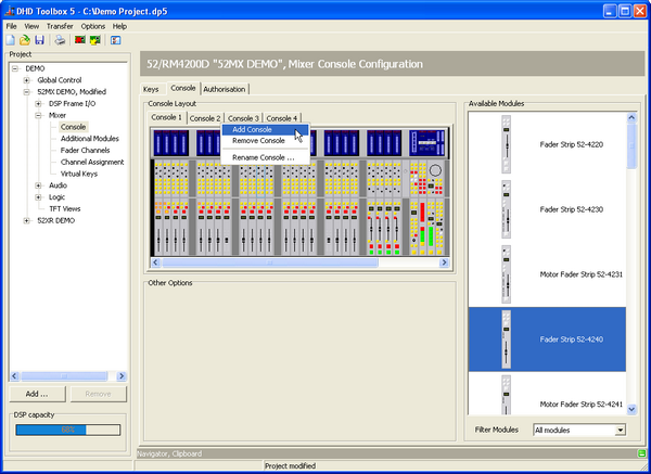
To add a console, in the Console Layout area, right-click on any of the console tabs in the Console View area. Select Add Console from the contextual menu. You can create up to 14 different consoles per DSP frame.
To remove a console, in the Console Layout area, right-click on the console tab you want to remove. Select Remove Console from the contextual menu.
To rename a console, in the Console Layout area, right-click on the console tab you want to rename. Select Rename Console from the contextual menu. A Rename Console window opens. Enter the new console name in New Label box. Click OK.
Keep in mind that splitting the modules to different consoles does not mean splitting of the mixer functions. Independent from the number of consoles, all have access to the same busses and fader signals. The splitting of the mixer into separate consoles is for organisational reasons only. If you want to operate another independent console in a DSP frame, find further information in Virtual Mixers.
Note
The graphical layout of the consoles is only important for printing the mixer view, otherwise it is mainly a visualisation of the mixer for the software users. For the configuration itself, the positions of the modules are not important.
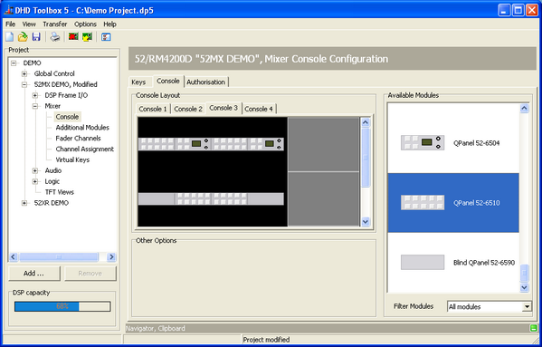
To insert a Q-Panel module to the console layout, it is necessary to insert them into a blank console layout. Drag a Q-Panel module to the console layout, the background of the view changes to a Q-Panel mounting frame automatically. It is also not possible to add console modules to a Q-Panel.
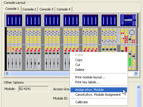
If there are already modules in the rack, you can open a contextual menu by right-clicking on the mounting slots.
To reorganise the modules in your console layout, use drag & drop, cut and paste or copy and paste. If the modules already have functions and labeled keys, this configuration is transferred to the copy of a module.
In the contextual menu of a module, you find the commands Print module layout and Print key labels. Use them to either print the complete module view including the assigned labels or just the key labels.
In the contextual menu of a module, you find the function Assign physical Module. Use this function to match your console layout to the physical console. This assignment defines which hardware module corresponds to which configured software module. You have to do this assignment for each console module (52/RX, 52/SX, RM4200D) or each module group (52/MX) as well as each TFT display.
Important
Make sure the console is switched on and has network access, before executing this command.
After clicking Assign physical Module, the selected module or a group of modules start flashing in the console layout. At the same time, at least one key flashes on each available module of the physical console and ASSIGN buttons are shown on the TFT displays. Now press a key on the module or the ASSIGN button on the TFT display that you want to match to the software module from where you called the Assign physical Module command. This way, the function is automatically terminated and you have assigned the selected graphical module to the corresponding hardware.
To cancel the Assignment procedure right-click on an module in the console layout and select Cancel physical Module Assignment.
In the contextual menu of a module you can find a Calibrate command.
Use the Calibrate command to adjust the 0 dB fader positions and to appoint the touch sensitive area of TFT displays.
Note
Only the faders of the RM4200D surface can be calibrated. Calibrating faders of a 52/MX mixing desk does not affect the mixer in any way.
Calibrating faders: Set all faders of a fader module to 0 dB (as accurately as possible). Right-click the respective module in the console layout and select Calibrate from the contextual menu. Now, all faders of this module are set to the new value. Repeat this procedure for all other fader modules.
Calibrating TFT displays: Right-click the desired TFT display in the console layout and choose Calibrate in the contextual menu. Now, you can see a cross in one of the physical TFT displays corners. Press this cross as accurately as possible and do the same for the crosses that will appear in the other corners of the display. Repeat this procedure for all other TFT displays.
When inserting the modules in the console view, you have to mind the following:
- RM4200D Fader overbridge modules can only be used with a fader module. You can only configure one overbridge module for each fader module. To configure the overbridge modules RM420-023 and RM420-028, you first have to insert the corresponding fader module RM420-029 or RM420-020 below.
- If you set up the blank modules RM420-022, RM420-022-O or the blind stripes 52-4490, 52-4590 and 52-4592 in the console, this only affects the printout and the monitor view of the console.
- Toolbox5 assigns automatically DSP resources for every inserted fader module. These DSP resources are necessary for the input processing. One stereo processing is needed per fader. In this case, only empty DSP processings and the necessary routing channels are assigned to the bus system. If you assign specific DSP functions to the fader channel, the DSP load increases again.
Important
You have to configure at least two DSP modules, if you want to use 24 or more faders. Beginning from 16 faders, you should use two DSP modules to have sufficient computing power for input and fixed processings available. From 32 faders and more you should use three DSP modules.
Setting up Module Options
In the Module Options area of the Console and the Keys tab, you can adjust the following features for the modules currently selected in the console layout. Keep in mind that Module Options are only shown if no key of the module is selected.
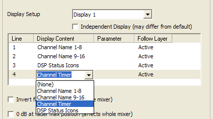
Module: Shows the name of the module. This value can not be changed.Access Group: Select to which access group the module should belong. All modules of the same access group cooperate for certain functions, for example when you create parameters for a fader channel on the central console. There are four access groups.Module ID: Shows the unique identification number of the module in the system. This value can not be changed.Description(control modules and 52/MX overbridge modules only): This description is shown in the displays of the control modules. The description should simplify the identification during the further configuration. The description overwrites the module ID. Type a space character in the Description box to set the display to off by default.Overbridge mode(52/MX overbridge modules only): The overbridge modules which are situated above control modules are always assigned as control modules automatically. You can choose for the overbridge modules above faders whether it should be a fader overbridge module or a control module (master overbridge).Display Setup(52/MX, 52/RX and 52/SX fader modules only, at XC/XS devices it is required to select the display in the module preview): The displays of the Series 52 fader modules are able to show four lines. In the table you can define which content is shown in the several lines. Click on the content of a line to open a list and select the desired content for each line. You can create different setups for single channels by activating the functionIndependent Displayfor these channels.
Invert fader scale(fader modules only): Invert the faders of the whole mixer. To close a fader, you have to move it to the upper position. To open, you have to move it to the lower position. DHD offers an appropriate front plate for the fader module RM420-020.0 dB at fader max position(fader modules only): Shift the scale of all fader modules in a mixer by 10 dB, so the fader has an amplification of 0 dB on the top position. Please note that the labelling of the front plate can not reflect this shift, it remains unchanged.Fader Speed(52/MX, 52/RX fader modules only): Set the speed of motorised faders during automatic movements likeChannel Start ON/OFFor layer switching.Default Display Text(RM4200D control modules only): Select one of the preset display options from the drop-down list (RM4200D <Firmware-Version>, <Device Name>, Timer 1…6 or Module <Description>). * Display follows menu (control modules only, at XC/XS devices it is required to select the display in the module preview): If the Display follows menu check box is disabled, the text in the displays of the control modules is static. If the check box is enabled, information on the current process is shown. The check box is activated by default.Selector(RM4200D control modules only): A selector for modules with hardware selector access (selector display and corresponding rotary encoder) can be defined here.Allow Selector Shift(RM4200D control modules only): If this check box is enabled, the selector is shifted if aMonitor Bus Shift keyis pressed.Unassigned Talkback Connections: In this area, you can see the available talkback sources and destinations which are not assigned. Drag an unassigned talkback connection from the list and drop it to a desired key in the Module area. (Drag & drop only on theKeystab available) Now, the talkback connection is directly assigned to that key.
The displays of the 52/MX / 52/RX control modules are operated in a split mode. Therefore, the displays can show the values of two functions simultaneously.
The Module-ID of each module is unique in a DHD system and allows the correct communication of the modules among each others. The configurable operating modules of the 52/MX and the RM4200D can be separated into the following functional groups:
| Fader Modules and Fader-Overbridge Modules | Modules and Control-Overbridge Modules | Displays (52/MX only) | Q-Panels (52/MX only) |
|---|---|---|---|
| 52/MX: IDs #F1 to #F48 RM4200D: IDs #F1 to #F48 | 52/MX: IDs #C C1T0S0 to #C C14T8S3 (#C CxTySz with 1≤x≤14 (console), 0≤y≤8 (module group) and 0≤z≤3 (position in the module group)) \\RM4200D: IDs #C1 to #C42 | Central Displays: IDs #CTFT C1T1 to #CTFT C14T8 (#CTFT CxTy with 1≤x≤14 (console), 0≤y≤8 (module group)) Fader Displays: IDs #FTFT C1T1 to #FTFT C14T8 (#FTFT CxTy with 1≤x≤14 (console), 0≤y≤8 (module group)) | IDs #C C1T0S0 to #C C14T2S3 (#C CxTySz with 1≤x≤14 (console), 0≤y≤8 (module group) and 0≤z≤3 (position in the module group)) |
| 52-4220 | 52-4401 | 52-4015 | 52-6504 |
| 52-4230 | 52-4402 | 52-6510 | |
| 52-4231 | 52-4404 | ||
| 52-4240 | 52-4410 | ||
| 52-4241 | 52-4411 | ||
| 52-4250 | 52-4412 | ||
| 52-4260 | 52-4421 | ||
| 52-4261 | 52-4422 | ||
| 52-4302 (Overbridge) | 52-4424 (Speaker Module) | ||
| 52-4304 (Overbridge, TFT Control Module) | 52-4302 (Overbridge) | ||
| 52-4306 (Overbridge, TFT Control Module) | 52-4304 (Overbridge) | ||
| 52-4505 (Overbridge) | 52-4306 (Overbridge) | ||
| 52-4516 (Overbridge) | 52-4505 (Overbridge) | ||
| 52-4527 (Overbridge, Speaker Module) | 52-4516 (Overbridge) | ||
| RM420-020 | 52-4527 (Overbridge, Speaker Module) | ||
| RM420-029 | RM420-010 | ||
| RM420-023 (Overbridge) | RM420-012 | ||
| RM420-028 (Overbridge) | RM420-013 | ||
| RM420-014 | |||
| RM420-025 (Overbridge) | |||
| RM420-026 (Overbridge) | |||
| RM420-027 (Overbridge) | |||
| RM420-078 (Overbridge) |
You can insert in an RM4200D console, up to 12 fader modules. In an 52/MX you can insert, up to 48 fader modules. These fader have automatically assigned module IDs. For the RM4200D the IDs are: from left to right #F1 to #F12. For the 52/MX the IDs are: from left to right #F1 to #F48. The fader overbridge modules are an extension of the corresponding fader module, and have the same ID as their fader module.
The control modules have also automatically assigned module IDs after inserting in the console layout. The control overbridge modules are an extension of the corresponding control module and have the same ID as their control module.
You can see the automatically assigned address of a module in the Module ID box.
The selection of the access group for a module defines with which other modules it cooperates for operation and display. All modules of the same access group cooperate, modules with different groups do not. You can choose between four access groups.
Key Configuration
On the Keys tab, you can assign the desired functions and labels to the fader and control modules.
To configure keys of fader and control modules, follow these steps:
- Select the desired module in the console layout. The selected module is now surrounded by a blue border. In the
Modulearea, you see a large view of this module. - In the
Modulearea, click on the key, which you want to configure. Now you can see on the Keys tab, a new Key Options area. - In the
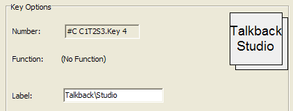
Key Optionsarea, enter a label for the key in the Label box. This label is later used as printout for the label key caps. To get a forced line break in the key label, enter a backslash (\). - On the
Viewmenu, selectKey Functions. TheKey Functionswindow opens. - Select the desired key function and drag it to the key preview in the Key Options area, or to the (
No Function) text, or to the desired key in the Module area. According to the selected key function, additional parameters for the configuration of the key may appear in theKey Optionsarea.
The keys on the fader modules can be configured with the key functions for fader modules, independent from the position and layout of the keys. (See Fader Modules)
The keys on the control modules can be configured with the key functions for control modules, independent from the position and layout of the keys. (See Control Modules)
If you have assigned a key function to a key, always a Colors area appears in the Key Options area. Set the logic sources which lead to the lighting conditions of the key.
Depending on the selected key function, you can define here, with which color the key shall light up according to the lamp source. On is the color if the function is enabled, Off if the function is in inactive condition. For the last case, mostly the Off option is used, for example the key does not light up. Depending on the selected key function, you find also different names in the Lamp Source column, for example Standby, Available, Busy, Owned, Layer A, Layer B or the name of the selected lamp source.
For the small keys of the modules, you can define the colors red and yellow. The large keys can light up in red, yellow and green. You can define flashing colors for the keys. Select the ![]() check box, in the
check box, in the Colors area.
Note
For the large keys of the modules 52-4220, 52-4250 and 52-4261 yellow is not available as an option. You can use a mixed color instead which corresponds with yellow. This is due to the fact that yellow is not generated by a separate LED but is a mix from red and green. Depending on the tolerance of the components, the key color can differ between the keys.
There are differences in the coloring of the keys - depending on the kind of used components. Certain keys can change the color display by software controlling, others can only be configured using colored key caps. Depending on the key, you can define during configuration, which color the key should have in certain conditions.
52/MX and 52/RX key types
For the 52/MX and 52/RX, at present three different types of keys are used:
| type | lighting conditions | illuminant | software-configurable color | keyface / travel | manufacturer / name |
|---|---|---|---|---|---|
| standard, small | red | LED | Yes | 12 mm x 12 mm / 4.5 mm | eao Lumitas, Series 95 |
| yellow | LED | ||||
| standard, large | red | LED | Yes | 18 mm x 18 mm / 4.5 mm | eao Lumitas, Series 95 |
| yellow | LED | ||||
| green | LED | ||||
| keys below fader of 52-4230, 52-4231, 52-4250, 52-4260, 52-4261, 52-2020 and 52-2029 | red | LED | Yes | 17.4 mm x 17.4 mm / 4.5 mm | NKK, KP Series, counter-sunk |
| green | LED | ||||
| red/green mixed | LED |
RM4200D key types
For the RM4200D, at present three different types of keys are used:
| type | lighting conditions | illuminant | color options for caps | software-configurable color | keyface / travel | manufacturer / name |
|---|---|---|---|---|---|---|
| standard, small | red | LED | clear, pearl (no options) | Yes | 12 mm x 12 mm / 4.5 mm | eao Lumitas, Series 95 |
| yellow | LED | |||||
| standard, large | red | LED | clear, pearl (no options) | Yes | 18 mm x 18 mm / 4.5 mm | eao Lumitas, Series 95 |
| yellow | LED | |||||
| green | LED | |||||
| keys below fader of RM420-020 | red | LED | red, glossy | No | 21 mm x 15 mm / 3.5 mm | eao Lumitas, Series 51, counter sunk |
| yellow | LED | yellow, glossy | ||||
| yellow | LED | clear, glossy | ||||
| green | LED | green, glossy |
In addition to the lighting conditions listed in the table, all keys can also be Off.
Please note that the LED color of the standard keys is defined in the Config and can change according to the logic state during operation. Therefore, the key caps have to be clear. As far as the configuration of the standard keys is concerned, the colors refer to LEDs and not to color transparencies.
There is a difference with the keys below the faders of an RM420-020 module. If you select a color for these keys, this is for information only which LED color and color of the key cap is to be inserted during manufacturing the module. These keys can only have the color ordered from DHD. During configuration, the colors refer to the color of the key cap, DHD uses the illuminant according to the table. Further options can not be ordered.
Authorisation - Limiting Access to Keys
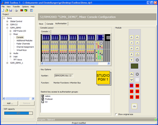
On the Authorisation tab, you can assign authorisation groups to certain keys. Use these authorisation groups to deny a user group access to certain keys. You have to create the appropriate authorisation groups previously. (See Administration)
On the Authorisation tab, you see the modules of the console in a minimized view. Keys that have been assigned to an authorisation group are shown red, not assigned keys grey. All grey keys can be used by all console users without entering a PIN.
Important
You can limit access to keys if you have already set up authorisation groups. In addition, on the Console tab, you should have labelled the desired keys. Otherwise, you can not limit access!
To assign a key to authorisation groups, follow these steps:
- In the
Console Layoutarea, select a module. In theModulearea you can see an enlarged view of that module. - In the
Module area, select the key you want to limit access for. A Key Options area appears. - In the
Key Optionsarea, you can see aRestrict key accesstoauthorisation groupslist with authorisation group check boxes. Select the authorisation groups, which have access to that key. The selected key becomes red and (only on this tab) shows the restricted access.
Important
If you use keys of the console for enabling PIN entry, please make sure that no authorisation group is assigned for these keys, otherwise you can not log in at the console!
Fader Modules
All functions that you can configure for fader modules and fader overbridge modules are described in this subsection.
Note
The configurable key functions for fader modules and control modules are different!
To configure a key, see Configuring keys of fader and control modules.
If you define a function for a key on a fader module, this function is assigned for the same key on all neighbour fader modules of the same type. If you change the function of a key, the appropriate keys of the other fader modules change as well. You can stop this coupled behavior for each key. To do this, select the Independent Key check box in the Key Options area.
You can use the Independent Key option for example for a fader with statically assigned sources or if you want to physically offset a fader module, for example for an independent operator.
Depending on the function you chose for a key, in the Key Options area, additional options are shown.
Functions Description
In the following tables, you find all available Key Functions plus their options or sub-functions.
The functions that can be assigned directly to the encoders of fader modules are identical to the options of the Encoder Function Set function.
(No Function)
| option or sub-function | selection | description |
|---|---|---|
| • no function, labeling for printout is possible |
Channel Functions
| option or sub-function | selection | description |
|---|---|---|
| Channel ON | • The channel is switched on. • By default, audio signal and fader start are enabled. In the Fader Channels subsection in the project tree, on the Advanced tab, you can set additional options (On Start, Auto Off and Level) in the Fader Start area. (See function Faderstart) |
|
| Channel OFF | • The channel is switched off. • By default, audio signal and fader start are disabled. In the Fader Channels subsection in the project tree, on the Advanced tab, you can set additional options (On Start, Auto Off and Level) in the Fader Start area. (See function Faderstart) |
|
| Channel ON/OFF | • The channel is toggled on and off using the same key. • By default, audio signal and fader start are switched on and off. In the Fader Channels subsection in the project tree, on the Advanced tab, you can set additional options (On Start, Auto Off and Level) in the Fader Start area. (See function Faderstart) |
|
| PFL | • Routes the signal to PFL bus 1. | |
| Momentary | • The function is enabled as long as the key is pressed. | |
| Toggle | • This key is stay put. | |
| Timed Toggle | • This key is stay put (short press) or spring return (long press). | |
| PFL2 | • Routes the signal to PFL bus 2. | |
| Momentary | • The function is enabled as long as the key is pressed. | |
| Toggle | • This key is stay put. | |
| Timed Toggle | • This key is stay put (short press) or spring return (long press). | |
| Solo In Place | • Mutes all channels except the channel where the pressed key is located. • In addition it is possible to configure fader channels not to react on the Solo In Place function. Therefore, select the Solo Effect Return check box (Fader Channels–>Fader Logic tab). (See function Solo Effect Return) |
|
| Momentary | • The function is enabled as long as the key is pressed. | |
| Toggle | • This key is stay put. | |
| Timed Toggle | • This key is stay put (short press) or spring return (long press). | |
| Direct Input Select | • Fader is fed with another fader channel. | |
| Layer | • Toggling between Layer A and Layer B. |
|
| Encoder Function Set (for 52-4302-1, 52-4302-2, 52-4250, Overbridge 1-4, RM420-029) | (No Modification) | • No change. |
| (No Function) | • No function assigned. | |
| AGain | • The corresponding encoder controls the analog gain value. | |
| Gain | • The corresponding encoder controls the digital gain value. | |
| DGain/AGain | • The corresponding encoder controls the digital gain value or after pushing on the encoder the analog gain value. | |
| Pan/Bal | • The corresponding encoder controls the panorama / balance. | |
| Timer | • The corresponding encoder adjusts a channel timer. | |
| Aux Gain | • The corresponding encoder controls the gain value of an Aux bus. | |
| EQ Gain | • The corresponding encoder controls the filter gain. | |
| EQ Frequency | • The corresponding encoder selects the frequency of a filter. | |
| Input Select | • The corresponding encoder selects an input. | |
| CF Output Select | • The corresponding encoder selects a clean feed output. | |
| CF In | • The corresponding encoder controls the clean feed level at the input of a preparation matrix. | |
| CF Out | • The corresponding encoder controls the clean feed level at the output. | |
| SubSonic Frequency | • The corresponding encoder selects the cutoff frequency of the subsonic filter. | |
| VarFilter Frequency | • The corresponding encoder selects the cutoff frequency of the variable high-pass/low-pass filter. | |
| Delay | • Assigns the function Delay to the encoder (if module RM420-424 is built in and configured). | |
| Stereo Width | The corresponding encoder controls the stereo width. | |
| Stereo Direction | The corresponding encoder controls the stereo direction. | |
| Input/DGain/AGain/PanBal | By pressing the encoder, the encoder control toggles between Input, digital gain value, analog gain value and panorama / balance. | |
| DGain/AGain/PanBal | By pressing the encoder, the encoder control toggles between digital gain value, analog gain value and panorama / balance. | |
| Channel Start ON | • The channel is switched on: Sets the channel to 0 dB. If the channel has a motor fader, this is automatically set to the 0 dB position. Otherwise, arrows in the display indicate that the fader position does not comply with the current value. Note The motor fader requires some time to get to the appropriate position. The audio signal is not affected, though! It is switched to 0 dB or -∞ dB immediately after pressing the key. |
|
| Channel Start OFF | • The channel is switched off: Sets the channel to -∞ dB. If the channel has a motor fader, this is automatically set to the -∞ dB position. Otherwise, arrows in the display indicate that the fader position does not comply with the current value. Note The motor fader requires some time to get to the appropriate position. The audio signal is not affected, though! It is switched to 0 dB or -∞ dB immediately after pressing the key. |
|
| Channel Start ON/OFF | • By pressing the key and the function is not active, the channel is switched ON: Sets the channel to 0 dB. If the channel has a motor fader, this is automatically set to the 0 dB position. Otherwise, arrows in the display indicate that the fader position does not comply with the current value. After pressing the key again, the channel is set to -∞ dB. If the channel has a motor fader, this is automatically set to the -∞ dB position. Otherwise, arrows in the display indicate that the fader position does not comply with the current value. Note The motor fader requires some time to get to the appropriate position. The audio signal is not affected, though! It is switched to 0 dB or -∞ dB immediately after pressing the key. |
|
| Memo | • This function is intended for the use as memory hook. You can switch the lamp of the key ON and OFF. The lamp switches OFF by opening the fader of this channel. • Keys with the Memo function are used to mark channels the DJ wants to start next. | |
| Tally | • The lamp in the key indicates the state ON, if the fader is open. The key function itself is unused. | |
| Channel ON (Ext) | • This function is a mixture of the functions Channel ON and Channel Start ON. It is possible to switch between these two functionalities with the aid of a logic function (see Operation Mode / Extend Channel On when). Normally the Channel ON function is used, but if the logic is true the Channel Start ON function is used instead. | |
| Channel OFF (Ext) | • This function is a mixture of the functions Channel OFF and Channel Start OFF. It is possible to switch between these two functionalities with the aid of a logic function (see Operation Mode / Extend Channel On when). Normally the Channel OFF function is used, but if the logic is true the Channel Start OFF function is used instead. | |
| Channel ON/OFF (Ext) | • This function is a mixture of the functions Channel ON/OFF and Channel Start ON/OFF. It is possible to switch between these two functionalities with the aid of a logic function (see Operation Mode / Extend Channel On when). Normally the Channel ON/OFF function is used, but if the logic is true the Channel Start ON/OFF function is used instead. | |
| Reset DSP Param | • Resets all selected DSP values of this channel to the default value. | |
| Select DSP Function to reset | • Select in this area, which DSP function is reset by pressing this key. |
Access Functions
| option or sub-function | selection | description |
|---|---|---|
| Access Gain | • The fader strip is assigned to the central control unit in Access Mode, Digital Gain is enabled as first parameter.• Use the main rotary controller in a control module of the same Access Group to modify Digital Gain without pressing any other key; the system function Gain is automatically selected.• This function is useful for modules that have no rotary controller of their own to modify the gain parameters. |
|
| Access Input Select | • The fader strip is assigned to the central control unit in Access Mode, the selection of the Fader Inputs is enabled as first parameter. • Use the main rotary controller in a control module of the same Access Group to modify Fader Input without pressing any other key; the system function Input Selection is automatically selected.• Operation is always locked if a fader is open. (Display: Input locked)! |
|
| Access PAN/BAL | • The fader strip is assigned to the central control unit in Access Mode, Panorama/Balance is enabled as first parameter. • Use the main rotary controller in a control module of the same Access Group to modify Panorama and Balance without pressing any other key; the system function Pan/Bal is automatically selected. |
On/Off Functions
| option or sub-function | selection | description |
|---|---|---|
| Phantom Power | • 48V phantom power, RM420-122 and RM420-123 only. | |
| Phase | • Phase reverse (in stereo signals right channel only). | |
| LL | • In stereo signals, the left input signal replaces the right. | |
| RR | • In stereo signals, the right input signal replaces the left. | |
| RL | • In stereo signals, change of left and right input signals. | |
| Mono | • Mono summation of the input signals in stereo inputs. | |
| Mono -3 dB | • Mono summation -3 dB of the input signals in stereo inputs. | |
| Mono -6 dB | • Mono summation -6 dB of the input signals in stereo inputs. | |
| LFE Only | • Surround mix (all surround channels incl. LFE) or LFE only. | |
| Sub Sonic | • Subsonic filter on/off (if configured). | |
| Var. LP/HP | • Variable High pass/Low pass on/off • Device Number 1 and 2, if two filters are configured. Both filters are affected anyway. | |
| EQ | • Equalizer on/off (Nr. 1 to Nr. 4, if configured). | |
| AGC | • Automatic Gain Control AGC on/off (if configured). | |
| Compressor | • Compressor on/off (if configured). | |
| Expander | • Expander on/off (if configured). | |
| Limiter | • Limiter on/off (if configured). | |
| Noise Gate | • Noise gate on/off (if configured). | |
| Deesser | • Deesser on/off (if configured). | |
| Deesser 2 | • Deesser 2 on/off (if configured). | |
| Insert | Insert number 1…16 | • Activates the signal path over one of the 16 possible switchable insert points. • Switching is exclusive, each switchable insert point can be activated for one fader only! (see also Switchable Inserts) |
| Delay | • Delay function is switched on and off (if delay module RM420-424 is built in and configured). • Signal path over RM420-424 remains active also in switched off state (Delay = 0). | |
| Display Channel Timer | • Shows the channel timer in the fader module display. The channel timer is started, stopped and reset by the fader start (On, Off) of the channel. Note This function is only useful with the module RM420-020 (RM4200D). |
|
| Bypass | • Bypasses the input processing of the channel (EQs, Compressor etc.). | |
| CF Preparation | • This function is similar to the cleanfeed function Preparation CFE. The difference is that this function is also inverse useable as central function. Both, the On/Off function and the cleanfeed function, are included in the Toolbox5 to keep newer software versions compatible to older configurations. | |
| CF Output Select | • This function is similar to the cleanfeed function Output Select CF. The difference is that this function is also inverse useable as central function. Both, the On/Off function and the cleanfeed function, are included in the Toolbox5 to keep newer software versions compatible to older configurations. | |
| CF N-Mix | • This function is similar to the cleanfeed function CF N-Mix. The difference is that this function is also inverse useable as central function. Both, the On/Off function and the cleanfeed function, are included in the Toolbox5 to keep newer software versions compatible to older configurations. | |
| VCA Fader | VCA Fader 1…8 | • The faders potentiometer value is coupled with a VCA fader value. You can use this function to group a number of faders to control them with one single fader. VCA channels do not sum fader signals into a new, grouped signal. (See Fader Channels / VCA Faders) • It is not possible to route a VCA channel to an other VCA channel. |
| Combined Logic | Combined Logic 1…4 | • Activates the combined logic (becomes true) for this fader channel. |
Bus Functions
| option or sub-function | selection | description |
|---|---|---|
| Voice | • Routes the signal to the internal Voice bus. If the signal is not routed to the voice bus, it is automatically routed to the music bus. |
|
| Off Air | • Routes the signal to the internal Off Air bus. |
|
| Program Bus | • Routes the signal to the internal Program bus. |
|
| Aux Bus | • Routes the signal to the internal Aux bus. |
Cleanfeed Functions
| option or sub-function | selection | description |
|---|---|---|
| Preparation CF | • Routes the channel to the preparation conference. (Preparation Mode) • Activates the logic source Source/Clean Feed/CF Prep <Name of Input>. • The created logic source can also be used in any other location in the system. |
|
| ON- Preparation Reset | • An enabled preparation routing is disabled when opening the fader. • Check box not selected: After closing the fader, the clean feed returns in preparation mode. Check box selected: Function is reset when opening the fader. • Color Off is ignored with this function. | |
| Talk CF | • Activates the logic source CF Talk <Name of Input> if a fader channel with enabled clean feed is routed to a fader. (See Fader Channels – Configuring Signal Sources) • The created logic source is to be configured as talk condition under <Device>/<Mixer>/Mixing Functions in the appropriate clean feed bus if the talk function is required. (See Mixing Functions – Configuring Internal Busses) • The created logic source can also be used in any other location of the system. |
|
| Momentary | • Function is enabled as long as the key is pressed. | |
| Toggle | • Key is stay put. | |
| Timed Toggle | • Key is stay put (short press) or spring return (long press). | |
| CF N-Mix | • Toggles the clean feed return signal between N-1 (OFF) and N (ON). | |
| Output Select CF | • Activates the output selector instead of the clean feed as outgoing signal if a fader channel with enabled clean feed is routed to the fader. (See Fader Channels – Configuring Signal Sources) • This function works only if a Output Selector Source List was assigned to the clean feed under <Device>/<Mixer>/Mixing Functions. (See Output Selector Source List) • In the assigned Output Selector Source List, at least one signal must be listed; if several signals are to be selected, a selection function must be configured. To do that, create a function Encoder Function/Output Select or System Function/CF Out in a control module. • Logic source Logic Source/Clean Feed/CF Output Select <Name of Input> is activated if a fader channel with enabled clean feed function is routed to the fader. • The created logic source can also be used in any other location of the system. |
|
| Cut CF | • The clean feed signal of the channel is muted. The talk signal is not muted. |
Fader Functions
| option or sub-function | selection | description |
|---|---|---|
| Fader Function | • Creates a logic source that can be universally used under Logic Source/Fader Function Channel/FF <Name of Fader Channel>.• Applications, for example talk button for clean feeds (instead of talk function described above), talk button for headphones assigned to microphones; realised via output functions. Faderstart On/Off for playout devices (via logic functions). |
|
| Momentary | • This function is enabled as long as the key is pressed. | |
| Toggle | • Key is stay put. | |
| Timed Toggle | • Key is stay put (short press) or spring return (long press). | |
| Fader Function 2 | • Creates a universally usable logic source under Logic Source/Fader Function 2 Channel/FF2 <Name of Fader Channel>.• Applications, for example talk button for clean feeds (instead of talk function described above), talk button for headphones assigned to microphones; realised via output functions. Faderstart On/Off for playout devices (via logic functions). |
|
| Momentary | • This function is enabled as long as the key is pressed. | |
| Toggle | • Key is stay put. | |
| Timed Toggle | • Key is stay put (short press) or spring return (long press). | |
| Fader Function Fader | • Creates a universally usable logic source under Logic Source/Fader Function Fader/FF Fader <Fader number>.• Application, for example fader related routing of sources to alternative PFL busses (Aux, Pre-Fader or Pre-Switched Mode) |
|
| Momentary | • This function is enabled as long as the key is pressed. | |
| Toggle | • Key is stay put. | |
| Timed Toggle | • Key is stay put (short press) or spring return (long press). |
TFT Views
| option or sub-function | selection | description |
|---|---|---|
| Show View | Set View | • In this list, a fader view is selected that can be configured under TFT Views. By pressing the key, the corresponding view is loaded. |
| Follow Access | • If this function is enabled, the content of the TFT display is overwritten by channel related contents, as soon as the Access key is pressed in a fader strip. • This function makes only sense on control modules. If this function is enabled on a fader module, it is not relevant. | |
| Access View | • If a key with the function Access View is configured, it can disable each Show View using Follow Access.Application examples: • In a master view a Show View button is configured with the Follow Access function (Button A) and a Show View button without Follow Access (Button B). • If button A is enabled, without the Access function being selected in a channel, the display does not change yet. • Button B is pressed. A new view is shown on the TFT, therefore Button A is not visible any longer, so Button A cannot be disabled. • If the Access key is now pressed in a channel, the view switches to the configured view of Button A. • Press the Access View key to disable the function of Button A and to keep the loaded view of Button B if the Access key is enabled in a channel. NoteThis function makes sense if several Show View Buttons are configured in TFT Views using the Follow Access function. Then, you need only one key with the Access View function to disable all Show Views. |
|
| Set Channel Views | • This function is not working and will be removed in one of the next Toolbox5 versions. | |
| Show Keyboard | • Opens a virtual keyboard on a defined TFT display. | |
| To Group | • Select from this list, on which TFT group the keyboard should open. | |
| Function | • Edit channel label: Use the keyboard to edit the label of a channel. • Login with keyboard: Instead of using a potentiometer to enter PIN numbers, you can use the keyboard to log in. |
TFT Displays
To configure a TFT display, in the project tree, select the subsection <device>/<Mixer>/Console. On the Keys tab, in the Console Layout window click on the desired TFT display. Now you can edit the characteristics of the selected TFT display in the Other Options area.
Module: Shows the name of the module. This value is preset by the selected TFT display (52-4015 or 52-4017), it can not be changed.Access Group: Select or enter an access group number to which the screen should belong. All modules of an access group cooperate for certain functions, for example when creating parameters for a fader channel on the central module.Module ID: In this box the unique identification number of the module in the system is shown.Description: You can type a description of the TFT display in this box. This description is automatically used asModule ID.TFT operation mode: To show the configured fader views on this TFT display, select the Fader Display option. You can also define the display as one of the 16 available central displays. SelectCentral Display 1…16to show Main TFT views on it. (See also TFT Views)Default View: If you configured the selected TFT display as a central display, you can define a Master View as default. This view is always shown if no other TFT view is selected.Access View: If you configured the selected TFT display as a central display, you can select a master TFT view that is shown, if an Access key is pressed.
Control Modules
In general, each key of a control module can be configured with any control module function, independent from its location and built.
Note
The configurable key functions for fader modules and control modules are different!
The flexible construction of the 52/MX and the RM4200D enables you to configure a great variety of functions. Therefore, only a few functions are described here in detail. As a supplement, you can obtain files with example configurations from DHD that you can look at in Toolbox5.
Note
For many functions, you have to configure keys as well in the fader module as in the control module. These functions are marked as ACCESS in the following table. In a fader module, the access key, for example always cooperates with the functions of a control module. This works only if both modules are located in the same access group.
Note
Some of the functions can only be used with control modules that have a display with at least 16 ASCII digits and the appropriate rotary pulse encoder. These functions are marked as DISPLAY in the following table. In addition, some functions may need an OK key to confirm or to reach the lowest menu level. These have the name OK. Please, also mind the access group setting of the used modules.
Important
If the cooperation of several modules is necessary for a function, they have to be located in the same access group. Therefore, when checking for errors, mind the correct assignment of access groups and modules! (See also Setting up Module Options)
To configure a key, see Configuring keys of fader and control modules.
Some functions are ACCESS and DISPLAY functions. In addition, some have more layers that you have access to by pressing a function key again or by pressing OK on the same module. In the table, these are numbered 1. (main level), 2. (2nd level), etc.
| name of the subfunction of system functions | selection | description |
|---|---|---|
| Gain | • Gain: Digital gain (-20 dB to +20 dB in steps of 1 dB). • AGain: Analog gain – RM420-122 and RM420-123 only (RM420-122: 0 dB to 50 dB in steps of 5 dB; RM420-123: 0 dB, 5 dB, 10 dB, afterwards in steps of 1 dB up to 70 dB). • Phasereverse: Phase reverse (ON, OFF) – only right channel if stereo. • Phantom: Phantom power 48V (ON, OFF) – RM420-122 and RM420-123 only. • Function does not make sense for modules with a separate rotary control and displays for the functions Gain and AGain. |
|
| PAN/BAL | • PAN/BAL: Panorama for mono and balance for stereo (L10 to R10 in 21 steps). • Channel: Channels exchanged in the sequence: L> L, R> R; L> L, L> R; R> L, R> R; R> L, L > R; Mono; Mono -3 dB; Mono -6 dB. |
|
| Input Selection | • Source selection from the assigned input pool of the fader, pool number and name of the source (Fader Channel Label) are shown. • Function works only with closed fader. • For faders with statically assigned source, the display shows no Pool . • If in a fader module, you already configured an Access Input Select function, you do not need this function key. The rotary control has the function Input Select immediately after pressing the Access key. This function is left as soon as you press a key with System Function or the Access key in the channel again. |
|
| Direct Input Select | * Select any audio source that you can use as input signal for the appropriate channel by pressing a key. This way, other audio sources on this channel are replaced automatically. | |
| Function Selection | • Operation of all configured functions in the fader strip using rotary control and OK button. • Useful for setting rarely used functions (e.g., 48 V Phantom power) to save on the corresponding keys. • You can not limit the menu with the available functions! • You have to configure an OK key for these functions! |
|
| CF In | • CF In Prep.: Routing of the channel to the preparation conference (ON/OFF). • CF In Gain: Input level into n-1 matrix (-40 dB to +15 dB in steps of 1 dB). • This function works for all sources, not only for fader channels with configured clean feed. |
|
| CF Out | • CF Out Gain: Output level of return line (-30 dB to +10 dB in steps of 1 dB). • CF Out Cut: Alternative signal (ON/OFF). • CF Out Mix: Switches between n and n-1 mix.• This functions works only for fader channels with clean feed. |
|
| Program | Program Bus 1…48 | • PGM n: Switches the program bus number n ON and OFF using the rotary control. • Function is not locked at open fader. |
| AUX | AUX Bus 1…48 | • AUX n Gain: Set Aux level of fader signal and output it to Aux bus n (off, -60 dB to +15 dB in steps of 1 dB). • AUX n Type: Toggles between the 3 Aux bus modes pre fader, after fader and switched pre fader (switched pre fader = Pre Fader - if fader is closed; off - if fader is opened). |
| Limiter | DSP Device Number 1 | • LIM: Switches the Limiter ON/OFF. • LIM Thr.: Threshold in the range of -20 dBint to +20 dBint (in steps of 1 dB). • LIM Rel.: Release time in the range of 3 dB/s to 20 dB/s (in steps of 1 dB/s). • The attack time can not be adjusted, it is always set to quick. |
| Compressor | DSP Device Number 1 | • COMP: Switches compressor ON/OFF. • COMP Thr.: Threshold in the range of -50 dBint to +10 dBint (in steps of 1 dB). • COMP Gain: Output gain in the range of 0 dB to +30 dB (in steps of 1 dB). • COMP Rat.: Ratio in the range of 1.0:1 to 5.0:1 (steps of 0.1). • COMP Att.: Attack time in the range of 0.2 ms to 50 ms (8 values). • COMP Rel.: Release time in the range of 0.05 s to 10 s (8 values). • This function makes no sense for the RM420-012 module, because it has a separate rotary control and displays for the compressor functions. |
| Expander | DSP Device Number 1 | • EXP: Switches the expander ON/OFF. • EXP Thr.: Threshold in the range of -50 dBint to +10 dBint (in steps of 1 dB). • EXP Gain: Output Gain in the range of 0 dB to +30 dB (in steps of 1 dB). • EXP Rat.: Ratio in the range of 1:1.0 to 1:5.0 (steps of 0.1). • EXP Att.: Attack time in the range of 0.2 ms to 50 ms (8 values). • EXP Rel.: Release time in the range of 0.05 s to 10 s (8 values). |
| EQ | DSP Device Number 1, 2, 3, 4; depending on the number of EQs | • EQ n Gain: Gain in the range of -15 dB to +15 dB (in steps of 1 dB) – not available for EQ type Notch. • EQ n Freq: Frequency in the range of 22 Hz to 20000 Hz (60 fixed preset values). • EQ n Qual: Quality in the range of 0.3 octaves to 3.0 octaves (in steps of 0.1 octaves) – not available for EQ type Hi/Lo Shelving. • EQ n Type: EQ type can be toggled between Bell, Notch, High Shelving and Low Shelving. • To get access to all equalizer bands (n=1…4) you have to configure one key for each band. • This function makes no sense for the RM420-012 and RM420-014 modules, because they have separate rotary encoders and displays for these functions. • The toggling through the EQ types is not noiseless! |
| AGC | DSP Device Number 1 | • AGC: Switches automatic gain control ON/OFF. • AGC Velo: Control speed in the range of 0.3 dB/s to 1.5 dB/s (steps of 0.1 dB/s). • AGC Gain: Max. signal shift in the range of 5 dB to 30 dB (in steps of 1 dB). • AGC Level: Set output level in the range of -20 dBint to 20 dBint (in steps of 1 dB). • AGC Thr.: Freeze threshold of the AGC in the range of -40 dBint to -20 dBint (in steps of 1 dB), for lower levels, the current or last value is recorded respectively. |
| Sub Sonic | DSP Device Number 1 | • SubS: Switches the subsonic filter ON/OFF. • SubS Freq: Cutoff frequency in the range of 32 Hz to 200 Hz (17 fixed preset values). • This subsonic filter is a 3rd order high pass filter (18 dB/octave). For other filter orders, please use the function Var. LP/HP. |
| Deesser | DSP Device Number 1 | • DeEs: Switches the deesser ON/OFF. • DeEs Rat.: Ratio in the range of 1.0:1 to 4.0:1 (in steps of 0.1). • DeEs Thr.: Threshold in the range of 1.0 to 1.8 (in steps of 0.1). • DeEs Bandw.: Bandwidth in the range of 0.2 to 0.5 (in steps of 0.1). This deesser is based on the principle of an adaptive filter. Note The threshold value refers to the sharpness of the sound. A low threshold value causes that the deesser will already work with few sharpness. |
| Deesser 2 | DSP Device Number 1 | • DeEs: Switches the deesser ON/OFF. • DeEs Freq.: Frequency in the range of 1000 Hz to 20000 Hz (28 fixed preset values). • DeEs Thr.: Threshold in the range of -40 dB to 10 dB (in steps of 1 dB). |
| NoiseGate | DSP Device Number 1 | • GATE: Switches noise gate ON/OFF. • GATE Thr.: Threshold in the range of -60 dBint to -10 dBint (in steps of 1 dB). • GATE Atn.: Attenuation in the range of 0 dB to 30 dB (in steps of 1 dB). • GATE Att.: Attack time in the range of 1.0 ms to 200 ms (8 values). • GATE Rel.: Release time in the range of 0.01 s to 2.0 s (8 values). |
| Var. LP/HP | DSP Device Number 1, 2 | • FILT n: Switches the variable Highpass/Lowpass filter ON/OFF. • FILT n Type: Filter type can be toggled between HighPass and LowPass. • FILT n Freq: Frequency in the range of 22 Hz to 20000 Hz (60 fixed preset values). • FILT n Order: Filter order can be set between 1st order (6 dB/octave) and 10th order (60 dB/octave). • You have to configure a separate key for each variable filter. • The toggling of the type and filter order is not noiseless! |
| Delay | • DELAY - Switches Delay ON/OFF. • DELAY - Delay between 0 s and maximum time, increment 10 ms. The maximum time depends on the selected number of channels of the RM420-424S in the DSP Frame I/O. (see also Delay Sub Module RM420-424S) • Each full turn of the rotary encoder means a change of 160 ms of the delay time. |
The option ON/OFF in a function can also be operated inversely. This means that you either select the desired channel first (ACCESS) and then press the ON/OFF key of a function or press the ON/OFF key of a function first. In the last case, the channels linked to the function indicate this assignment by lighting up the corresponding keys. This is especially useful for dynamic and routing functions.
Examples:
- First press the Access key in a fader strip. Now you can switch the corresponding key for the channel busses on and off in the control module.
- If instead no Access function is active in the fader strip, you can press and hold a key for assigning a bus in the control module. Now, the Access keys of all channels are lighting up that are assigned to this bus. So you can check quite quickly, which signals are routed to a certain bus. Functions like this are marked INVERSE in the following table.
Functions Description
(No Function)
has no function.
User Defined
| selection | description |
|---|---|
| • By right-clicking (not assigned) in the Lamp Source column, you can either select the key itself as a source or select any source from the logic sources window. • You can use the created logic source in many ways, for example for logic functions, output functions, global logic functions or routing to GPOs. • You can change the sequence of the three rows in the Colors area. Drag a row in the Lamp source column to its new priority place. • The LED with higher priority lights up if its lamp source is active; two colors can't light up at the same time! • The LEDs of the keys can also be used to show a condition without having assigned a key function. This is useful to do a test on GPIs. |
|
| Momentary | • The function is active as long as the key is pressed. |
| Toggle | • The key is stay put. |
| Timed Toggle | • The key is stay put (short press) or spring return (long press). |
Monitor Functions
| option or subfunction | selection | description |
|---|---|---|
| Monitor Bus | • Function for setting up alternating sets of monitor keys. • Monitor busses are not audio channels on the TDM bus system, but you can set them up internally via special routing functions! • Monitor keys are assigned to internal selectors. These can be created and edited under Audio/Monitor Functions - Selectors. • The created selectors can be selected as sources for output functions or for the output routing in the source window Audio under Monitor Functions. • Selectors can not be used as sources for other DSP functions, for example fixed processing. (To do this, you have to route them via an output function!) • Summed monitoring is not possible with this function, the keys are alternating. Only one source can be routed at the same time. • If you press the same key again, the monitor bus changes to the Default Source selected at Audio/Monitor Functions. The condition not assigned is preset (muting the bus). (See also Monitor Functions – Options for Monitoring) • Sets of monitor keys can also be operated and extended over several modules. • Monitor bus is useful to save keys. |
|
| Selector | • You can choose an available selector from this list. | |
| Allow Shift | • The selector is shifted if a Monitor Bus Shift key is pressed. | |
| Deny Switch Off | • The sources of the monitor bus can only cancel out each other. This way, one of the available monitor signals is always assigned to the monitor bus. | |
| Left Source | • Select an audio source from the TDM bus. | |
| Right Source | • Select an audio source from the TDM bus. | |
| Monitor Bus Shift | • Generally, the Monitor Bus keys influence the selector, that you have assigned to these keys during the key configuration. • By pressing the Monitor Bus Shift key, a different selector is chosen from the selector list, which now can be controlled by the Monitor Bus keys. The change is not to a defined selector, but the current selection is shifted by a selected value (Shift Offset) to a different selector. This shift is rising with reference to the serial number of the selectors. • After pressing the Monitor Bus Shift key again, the previous selection in the selector list is enabled again. |
|
| Shift Offset | • The chosen selectors can be shifted by 0 to 200 entries within the Available Selectors list. | |
| Rotary Selector | • After pressing the Rotary Selector key, you can select a source from a selector source list by an encoder. | |
| Selector | • Choose a selector, from the selector source list. | |
| Encoder | • Select an encoder which selects a source. | |
| Allow Shift | • The selector is shifted if a Monitor Bus Shift key is pressed. | |
| Potentiometer | • This function enables the operation of the potentiometer functions via key + rotary encoder in control modules. • Example: Create a software potentiometer and assign it to a bus as Master Level Control (in the project tree <Mixer>/Mixing Functions). Now you can use it to control the level of the bus with an encoder which you can select from the Encoder list (Key Options area) |
|
| Potentiometer | • Select a software (virtual) potentiometer from the list, to define which potentiometer will be controlled by an encoder. To create an software potentiometer select in the project tree <Device>/Audio. On the Potentiometer tab, create a new software potentiometer and name it distinctively. (See Potentiometers - Assigning Potentiometers) | |
| Encoder | • Select an encoder from the list. This encoder controls a software potentiometer, which you can select from the Potentiometer list. | |
| System Functions | • Please see the table above for information on system functions. |
Snapshot Functions
| option or subfunction | selection | description |
|---|---|---|
| Load Mixer Snapshot DISPLAY, OK | • Loads the saved settings of all defined fader channels of the mixer. In the <Mixer> subsection in the project tree, on the Snapshot Options tab, you can define a loading method. (See Snapshot Options) • You can select a snapshot between 0 and 20. |
|
| Save Mixer Snapshot DISPLAY, OK | • Saves the settings of all defined fader channels of the mixer. In the <Mixer> subsection in the project tree, on the Snapshot Options tab, you can define which parameters are saved. (See Snapshot Options) • You can select a snapshot between 1 and 20. • Write protection for mixer snapshots is not possible. • To save the mixer snapshot 0 (default setup) you have to use the maintenance window of Toolbox5. You should use mixer snapshot 0 with a sensible set of device presets. This is especially important for the analog gains of the microphones and phantom power. (See Maintenance Window) |
|
| Load Channel Snapshot DISPLAY, ACCESS, OK | • Loads the channel snapshot for the selected channels, which are selected by Access key. • You can select a snapshot between 0 and 250 (12 steps per encoder turn). • Channel snapshot 0 is an empty setup (all parameters are set to 0 dB and DSP processing is disabled). |
|
| Save Channel Snapshot DISPLAY, ACCESS, OK | • Saves the settings for the channels selected by its Access key. In the <Mixer> subsection in the project tree, on the Snapshot Options tab, in the Channel Snapshot Options area, you can define which parameters are saved. (See Snapshot Options) • You can select a snapshot between 1 and 250 (12 steps per encoder turn). • Write protection for channel snapshots is not possible. |
|
| Load Mixer Snapshot | Snapshot Nr. 0…20 | • Loads a specific mixer snapshot. In the <Mixer> subsection in the project tree, on the Snapshot Options tab, you can define a loading method. (See Snapshot Options) • The snapshot is loaded directly by pressing the respective key for about 1 second. |
On/Off Functions
| option or subfunction | selection | description |
|---|---|---|
| subfunction: all INVERSE | • All On/Off functions enable and disable features directly. | |
| Phantom Power | • 48 V phantom power, RM420-122 and RM420-123 only. | |
| Phase | • Phase reverse (in stereo signals right channel only). | |
| LL | • In stereo signals, the left input signal replaces the right. | |
| RR | • In stereo signals, the right input signal replaces the left. | |
| RL | • In stereo signals, change of left and right input signals. | |
| Mono | • Mono summation of the input signals in stereo inputs. | |
| Mono -3 dB | • Mono summation -3 dB of the input signals in stereo inputs. | |
| Mono -6 dB | • Mono summation -6 dB of the input signals in stereo inputs. | |
| LFE Only | • Surround mix (all surround channels incl. LFE) or LFE only. | |
| Sub Sonic | • Subsonic filter on/off (if configured). | |
| Var. LP/HP | • Variable High pass/Low pass filter on/off. • Device Number 1 and 2, if two filters are configured. Both filters are affected anyway. |
|
| EQ | • Equalizer on/off (Nr. 1 to Nr. 4, if configured). | |
| AGC | • Automatic gain control AGC on/off (if configured). | |
| Compressor | • Compressor on/off (if configured). | |
| Expander | • Expander on/off (if configured). | |
| Limiter | • Limiter on/off (if configured). | |
| Noise Gate | • Noise gate on/off (if configured). | |
| Deesser | • Deesser on/off (if configured). | |
| Deesser 2 | • Deesser 2 on/off (if configured). | |
| Program Bus | Program Bus 1…48 | • Routing of selected (by Access key) channels to a defined program bus. |
| Disable when fader ON | • Select the Disable when fader ON check box to lock this routing function if the fader is open! | |
| Aux Bus | AUX Bus 1…48 | • Routing of selected (by Access key) channels to a defined Aux bus. |
| Off Air | • Routing of selected (by Access key) channels to the Off-Air bus. • You can route a channel to the Off Air bus, only if the fader is closed. |
|
| Voice | • Routing of selected (by Access key) channels to the voice bus. | |
| Insert | Insert number 1…16 | • Assigns a switchable inserts to a channel. |
| Delay | • Delay on/off (if delay module RM420-424 is built in and configured). • Signal path over RM420-424 remains active, also in switched off state (Delay = 0). |
|
| Display Channel Timer | • Shows the channel timer in the fader module display. The channel timer is started, stopped and reset by the fader start (On, Off) of the channel. Note This function is only useful with the module RM420-020 (RM4200D). |
|
| Bypass | • Bypasses the input processing (EQs, compressor, etc.). | |
| CF Preparation | • Preparation mode on/off. | |
| CF Output Select | • Output select on/off. | |
| CF N-Mix | • Switches between n and n-mix. | |
| CF Cut | • Cut CF on/off. | |
| VCA Fader | • The faders potentiometer value is coupled with a VCA fader value. You can use this function to group a number of faders to control them with one single fader. VCA channels do not sum fader signals into a new, grouped signal. • It is not possible to route a VCA channel to an other VCA channel. |
|
| Combined Logic | Combined Logic 1…4 | • Combined logic on/off. |
Misc. Functions
| option or subfunction | selection | description |
|---|---|---|
| OK | • Confirmation key for several functions. | |
| Cancel | • Cancels a process. | |
| Layer Group | • Selects a group of physical faders that can be toggled to their secondary channel assignment by a key. | |
| Fader Range 1…64 | • Select or type the number of the first and the last fader module for this layer group. | |
| Layer | • Toggles a selected (by Access key) fader between layer 1 and layer 2. Function is only active if a channel is assigned to the second layer of the selected fader. | |
| Refresh Displays | • Refreshes all displays in the modules. | |
| PFL Reset | • Disables all PFL routings on all channels. | |
| Auto PFL | • If no channel is routed to PFL bus, the function enables PFL routing for all channels for which the Auto PFL function is enabled under <Mixer>/Fader Channels/Fader Logic. (See also • If PFL routings are enabled, and the Auto PFL key is pressed, the PFL routings of all channels are disabled. |
|
| Auto OffAir | • If no channel is routed to the Off-Air bus, the function enables Off-Air bus routing for all channels for which the Auto OffAir function is enabled under <Mixer>/Fader Channels/Fader Logic. • If Off-Air routings are enabled, and the Auto OffAir key is pressed, the Off-Air routings for all channels are disabled and all channels that have previously been in Off-Air mode are switched off. This is necessary to prevent sending signals of the Off-Air bus accidentally to the program bus when routing channels to a program bus while a fader is open. NoteIf no On keys are available in the channels, it is impossible to enable the channels again that have been switched off by the Auto OffAir function.To prevent this, under <Mixer>/Operation Mode - Off Air Options you can select the “Fader Start On” blocks “Off Air” switch off check box. Using this option, channels can only be switched to the On-Air mode from Off-Air mode if the faders are closed. |
|
| Encoder Function Set (for 52-4302-1, 52-4302-2, 52-4230, 52-4250, 52-4428 Overbridge 1-4, RM420-029) | (No Modification) | • No modification. |
| (No Function) | • No assignment. | |
| AGain | • The corresponding encoder controls the Analog Gain value. | |
| Gain | • The corresponding encoder controls the Digital Gain value. | |
| DGain/AGain | The corresponding encoder controls digital gain and analog gain (if the channel is a microphone channel). Push the encoder to toggle between these functions. | |
| Pan/Bal | • The corresponding encoder controls the panorama or the balance respectively. | |
| Timer | • The corresponding encoder controls the timer selection. | |
| Aux Gain | • The corresponding encoder controls the gain value of an Aux bus. | |
| EQ Gain | • The corresponding encoder controls the amplification of a filter. | |
| EQ Frequency | • The corresponding encoder controls the selection of the middle frequency of a filter. | |
| Input Select | • The corresponding encoder controls the input selection. | |
| CF Output Select | • The corresponding encoder controls the Clean Feed Output selection. | |
| CF In | • The corresponding encoder controls the Clean Feed level at the Input of the preparation matrix. | |
| CF Out | • The corresponding encoder controls the Clean Feed level at the output of the preparation matrix. | |
| SubSonic Frequency | • The corresponding encoder controls the selection of a separation frequency of the subsonic filter. | |
| VarFilter Frequency | • The corresponding encoder controls the crossover frequency selection. | |
| Delay | • Assigns the function Delay to the encoder (if module RM420-424 is built in and configured). | |
| Stereo Width | • The corresponding encoder controls the stereo width. | |
| Stereo Direction | • The corresponding encoder controls the stereo direction. | |
| Input/DGain/AGain/PanBal | • The corresponding encoder controls input selection, digital gain, analog gain (if the channel is a microphone channel), panorama or balance. Push the encoder to toggle between these functions. | |
| DGain/AGain/PanBal | • The corresponding encoder controls digital gain, analog gain (if the channel is a microphone channel), panorama or balance. Push the encoder to toggle between these functions. | |
| MIDI | • You can create up to 40 central MIDI keys. The functionality of these keys have to be assigned in the dbc MidiControl software. (Please see the MidiControl software manual for more information.) | |
| Show Original Channel Names | • It is possible to change the names of the fader channels within the snapshot manager software of the DHD Operation Manager. With this key, you can swap between the original and adapted name of the fader channel. | |
| Reset DSP Parameter | • Resets the selected DSP functions to the standard values. • One or several of the following DSP functions can be selected: EQ1, EQ2, EQ3, EQ4, SubSonic, Limiter, NoiseGate, Compressor, Expander, AGC, Var. LP/HP1, Var. LP/HP2, Gain, Pan/Bal and Delay. |
|
| Brightness | • Allows to change brightness level for console and/or TFT. Select Brightness key function and set Dim level (0=Off, 3=Max. Brightness). Important Brightness off (0) disables all keys, TFTs and potentiometers. Make sure you have always configured a Brightness on (values 1…3) key before defining a Brightness off key. Otherwise you can not turn on your console again. |
TFT Functions
| option or subfunction | selection | description |
|---|---|---|
| Show View | • Press this key to show a selected TFT view on a selected TFT display. | |
| Set View | • In this list, select a TFT view, which will be shown by pressing this key. | |
| To Group | • Select a display group from this list, on which the selected TFT view is shown. | |
| Follow Access | • The values which are shown in the selected TFT view, belong to the selected (by access key) channel. • Define a central display on which you show the functions of a channel in full screen mode. To do this, generate a master view that reflects the desired channel characteristics. |
|
| Access View | • Disables all shown TFT views, which are following an Access key. Example: • In a TFT master view, a Show View button with Follow Access option is configured (button A) and a second button without Follow Access (button B). • If button A is enabled without a selected Access key in a channel, the display does not change. • If button B is pressed, a new view shows up on the TFT display, thus making button A invisible. Therefore, also the function of button A can not be disabled. • If the Access key is now pressed in a channel, the view switches to the configured view of button A. • Press the Access View key, the function of button A is disabled and the view loaded by button B is kept if the Access key is enabled in a channel. Note This function makes sense if you have configured several Show View buttons with the Follow Access option in TFT views. Then, you only need one key with Access View function to disable all Show Views. |
|
| Set Channel Views | • This function switches the TFT fader views of a selected fader range to a desired view. | |
| Set View | • Select the fader view that should be shown. | |
| Physical Fader Range | • Choose a range of physical faders for that the fader view should change. • Set both values to 0 to affect the whole mixer. |
|
| Show Keyboard | • Opens a virtual keyboard on a defined TFT display. | |
| To Group | • Select from this list, on which TFT group the keyboard should open. | |
| Function | • Edit channel label: Use the keyboard to edit the label of a channel. • Login with keyboard: Instead of using a potentiometer to enter PIN numbers, you can use the keyboard to log in. |
Routing Functions
| option or subfunction | selection | description |
|---|---|---|
| • The keys are used for routing the signals of the TDM bus to an output or an output function. • One key should be reserved for each source and destination. • Routing can be mono and stereo, this depends on the configuration, but it is similar for all keys! Do not use mixed routing of mono and stereo signals! • If you press a source key, the correspondent destination keys are lighting up. • If you press a destination key, you can select a new source. The routing will be done immediately if no Take function is configured. To confirm the routing to the new source, press the Take key. |
||
| Input | Left Source | • Select any source from the Audio sources window for the left channel. |
| Right Source | • Select any source from the Audio sources window for the right channel. • If a routing function is used mono, no source selection for the right channel is necessary. |
|
| Output | Selector | • Choose a selector from the list. Selectors can be created and edited under Audio/Monitor Functions. |
| Use Take | • If you enable this check box, routing is done only after pressing the Take key. This option can be defined separately for each key. | |
| Take | • This key controls the optional Take function for the routing. It only needs to be configured once in every system. |
|
| Routing Selector | • Choose a selector. If a Selector Source List is chosen for this selector, the sources of this list are shown after pressing the Routing Selector key. Select this source with the encoder and confirm it by pressing Take. |
Resource Functions
| option or subfunction | selection | description |
|---|---|---|
| Resource Request | • The Resource Request key combined with the OK key allows a request to the corresponding free or occupied resource, the release from ownership (Release Mode) or the forced take over (Take Over, Special Take Over). • You should configure the key in two colors, for example red for ON and yellow for OFF. This way, you can create the following conditions: - Off: The resource is taken by another participant. - Yellow, constant: Resource idle. - Yellow, flashing: The assigned resource is requested and must be released by the owner. - Red, constant: The resources is self-owned. - Red, flashing: The resource is owned by oneself and is requested by somebody else. |
|
| Resource | • List of all configured project resources for which the current project is defined as a subscriber. (See also Global Resources) | |
| Reserve for | • List of all configured subscribers, for which a resource can be requested and reserved. |
Timer Functions
| option or subfunction | selection | description |
|---|---|---|
| Subfunctions: all DISPLAY | • A timer is shown in a module with display. • The corresponding display in the modules must be assigned a different Access Group using Console/Keys/Special (left-clicking on the module), to prevent the timer display to be toggled when pressing an ACCESS key! |
|
| Timer Start | Timer 1…6 | • Manual start of the timer. • From the timer box, select or enter the timer, which should started by pressing this key. |
| Timer Stop | Timer 1…6 | • Manual stop of the timer. • From the timer box, select or enter the timer, which should stop by pressing this key. |
| Timer Reset | Timer 1…6 | • Resets the timer to 0. • From the timer box, select or enter the timer, which should reset by pressing this key. |
| Timer Set | Timer 1…6 | • Use an encoder to set a return time (approx. 1 min per turn). • After reaching time 0, the timer jumps to the preselected time and counts upwards. • From the timer box, select or enter the timer, which should be set by pressing this key. |
| Timer Fader | Timer 1…6 | • The timer can be started by fader start. • Only the fader starts of the fader channels are working, in which a timer reset was enabled! (See Fader Channels – Configuring Signal Sources) • From the timer box, select or enter the timer, which should start by opening a fader. |
Talkback Functions
| option or subfunction | selection | description |
|---|---|---|
| Talkback | • Establishes a connection between a talk source and a talk destination. • Please see the example in the Virtual Keys section if you want to integrate external talkback panels of other manufactures or custom-made panels. |
|
| Source | • List of all talkback sources configured in the talkback matrix. (See also Talk) | |
| Destination | • List of all talkback destinations configured in the talkback matrix. | |
| Momentary | • The function is enabled as long as the key is pressed. | |
| Toggle | • The key is stay-put. | |
| Timed Toggle | • The key is stay-put (short press) or spring-return (long press). | |
| TalkbackReply | • The talkback member that is chosen at Source, calls the talkback member that has talked to this source last. |
|
| Source | • List of all talkback sources configured in the matrix. | |
| Momentary | • The function is enabled as long as the key is pressed. | |
| Toggle | • The key is stay put. | |
| Timed Toggle | • The key is stay put (short press) or spring return (long press). |
DelayNr DISPLAY
| option or subfunction | selection | description |
|---|---|---|
| Encoder | • Enables an encoder to control the values of a defined delay. Press the encoder to toggle between on/off function and delay time. • You can select the delay time in three different increments. When the delay time is shown in the display, turning the encoder changes the delay time in increments of 1 ms. Press the encoder, you can change the delay time in increments of 10 ms by turning the encoder. Press the encoder again, you can change the delay time in increments of 100 ms by turning the encode. |
|
| DelayNr | • In this list, select the delay which you want to control. |
Set Mixer Options
| option or subfunction | selection | description |
|---|---|---|
| • Use these key functions to change the PFL behavior. | ||
| PFL Mix | • Enables, that several channels can be simultaneously routed on PFL1. | |
| PFL Reset | • If the fader of any channel in PFL mode gets opened (it does not matter if the opened channel belongs to PFL bus 1 or 2), all currently active PFL1 routings are reset. | |
| PFL Reset Channel | • If a channel is routed on PFL1 and you open its fader, the PFL1 routing of that channel is reset. | |
| PFL Return | • If a channel is routed on PFL1 and you open its fader, the PFL1 routing of that channel is reset. If you close the fader, the PFL routing is reactivated. | |
| AFL When Fader On | • Toggles automatically the monitoring mode from PFL to AFL, if the fader of a channel is opened (Faderstart ON). |
The following functions can be assigned to the encoders of control modules directly:
| name of the function | option or subfunction | description |
|---|---|---|
| Potentiometer | • The encoder is used as a potentiometer. | |
| Potentiometer | • Choose a (virtual) potentiometer you want to control with the encoder (see Potentiometers - Assigning Potentiometers). | |
| Rotary Monitor | • The encoder is used as a rotary selector. | |
| Selector | • Choose a selector to be able to select the sources of a selector source list (see Monitor Functions - Options for Monitoring). | |
| Timer | • The encoder is used to enter the Timer Set values. | |
| Timer | • Choose a timer from the list you want to control with the encoder. | |
| Talkback List | • Use the encoder to select a talk destination from the talkback members list | |
| Talk Source | • Select a source to talk into. | |
| Delay | • The encoder controls the values of a defined delay. Press the encoder to toggle between on/off function and delay time. | |
| Delay | • In this list, select the delay which you want to control. | |
| Default Menu | • In this list, select the default menu which shows up in the display. |
Overbridge Modules 52-4505A-E, 52-4301, 52-4303 and 52-4305
The layout of the universal module 52-4505 can be adapted within the scope of a defined pattern. The module can feature up to 5 pushbuttons or up to 3 potentiometers. A specific and thus clear arrangement of the pushbuttons on the module surface contributes to improved ergonomics and operation. Omitting particular pushbuttons from a fully equipped module with 5 pushbuttons results in 31 different combinations.
The following layouts are already produced:
 |  |  |  |  |
| 52-4505A basis module | 52-4505B | 52-4505C | 52-4505D | 52-4505E |
The same applies to the modules with potentiometers. Based on a maximum of 3 potentiometers, there are 7 different combinations. Furthermore, the circuit board of the module can also be fitted into the mixing console without front panel, then being controlled by external potentiometers.
The following layouts are already produced:
 |  |  |
|
| 52-4303A basis module | 52-6509A for up to 3 external potentiometers | 52-4301A | 52-4305A |
The foil on the modules 52-4301A, 52-4303A and 52-4305A is imprinted with a default labelling in German. For other markings you can apply adhesive labels. Change requests concerning the original labelling can only be realised in connection with a minimum order and a delivery time of 12 weeks. For labelling changes or different module layouts it is necessary to contact DHD before ordering.
Important
In the Toolbox5 configuration software all variants mentioned above and to be available in the future are represented by the Overbridge Module 52-4505. The module 52-6509A is mounted beneath another overbridge module. However, it has to be configured as a separate module in the Toolbox5 software. Like any module, it needs an individual connection to a 52-4050 controller.
Overbridge Module RM420-013
The overbridge module RM420-013 has additional display elements and a chip card reader. The configuration of these additional functions is described in this subsection.
In the project tree, select <Device>/<Mixer>/Console. On the Console tab, drag the RM420-013 module from the Available Modules area to an empty slot in the Console Layout area. Select this module in your console layout. In the Other Options area, you can assign logic sources to the LEDs of the display elements MIC ON, ON AIR, PHONE 1 and PHONE 2.
Note
The labelling and the color of the LEDs can not be modified.
| name of the function | assigned element | description |
|---|---|---|
| MIC ON lamp source | Red LED-display labelled MIC ON. | • You can select any logic source, for example a logic function that is OR-linked with the fader starts of the microphones. |
| ON AIR lamp source | Red LED-display labelled ON AIR. | • You can select any logic source, for example a logic function or a GPI signal for OnAir-routing a studio to the studio transmitter line. |
| PHONE 1 lamp source | Yellow LED-display labelled PHONE 1. | • You can select any logic source, for example a logic function or a GPI with calling signal or status signal of the phone hybrid. |
| PHONE 2 lamp source | Yellow LED-display labelled PHONE 2. | • You can select any logic source, for example a logic function or a GPI with calling signal or status signal of the phone hybrid. |
RM420-013 overbridge modules that have been manufactured until May 2003 have an electromagnetic eject function for the chip card. For all modules produced later (from June 2003) the chip card has to be removed manually.
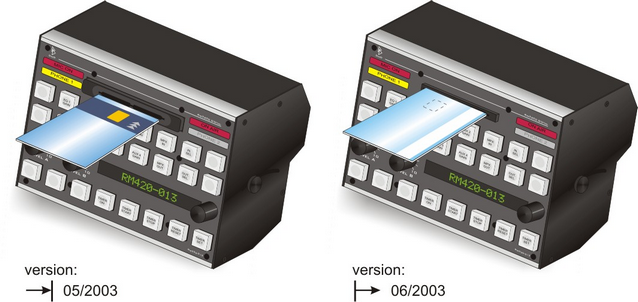
For card readers with electromagnetic eject, assign any logic source to the Card release source box which ejects the chip card. Often, the Eject Card key is used.