Mixing Functions - Configuring Internal Busses
You can configure the internal Busses for each virtual mixer separately. To do this, select the desired virtual mixer from the project tree and select the Mixing functions tab. On this tab, you can configure the number of summing busses, Aux busses, the talk functions and special functions of the clean feed system (N-1). Please keep in mind that clean feeds also claim summing bus resources. (See also Fader Channels – Configuring Signal Sources for Faders)
Dual MADI modules RM420-422S use several channels on the TDM bus system which are normally used for busses. Therefore, the configuration of these modules does influence the bus load and the DSP capacity respectively (see also MADI Modules).
The MADI module 52-1821 of an XC/XS Core, does not influence the DSP capacity like the RM420-422S in an RM4200D DSP frame.
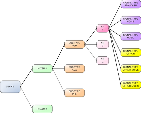
Mixing System
The configuration software Toolbox5 offers simple opportunities to realise complex bus structures within an Series 52 mixing device.
Busses are separated according to their Bus Type. You can create busses of the types Program, Aux and PFL. Two program busses and one PFL bus are available by default. You can delete these default busses or change their features. The total number of available busses depends on the DSP capacity of the system.
Important
When creating the busses, keep in mind that they affect the DSP load of the whole system. Therefore, do not create more busses than necessary to spare the resources for other applications.
Note
All summing busses are internally regarded as stereo, by mono-summation of the left and right channel, they can also be used mono. It is not possible though to create two mono summing busses from one stereo summing bus!
Summing Busses with certain Signal Types
When configuring the mixing functions you can distinguish summing busses according to certain signal characteristics, for example to the type of the signal. On some mixers, busses are identified according to the type of signal. We generally distinguish between voice signals (Voice) and other signals (Music), mix them separately and routes the sums to different signal processors (internal or external).
The Standard signal type is selected by default and defines a program bus which can be fed with fader signals via the key function Program Bus Nr. On/Off. The configured program busses are separated using the serial bus number.
Within the system, depending on the free DSP resources, up to 48 program busses can be configured.
Apart from this, there is an opportunity to change the type of signal, despite using busses with different serial numbers. The integrated additional functions influence the signalisation in the system and can be misunderstood. Therefore, this mode makes sense only in special applications.
Voice / Music / Off Air Switching
In broadcast mixers, program busses are often distinguished by the kind of signal they are fed with. The signals are separated into voice and music that are mixed on different busses and processed differently, before they go On Air. In addition, mostly there is a third so called recording bus (Recording or Off Air). Since firmware version 6.6.19 two additional bus types exist, Off Air Voice and Off Air Music. Busses with the Voice, Music, Off Air, Off Air Voice and Off Air Music signal types are fully featured sums, onto signals can be switched on exclusively. This means that fader signals can be fed either on Voice, Music, Off Air, Off Air Voice and Off Air Music.
Important
Using summing busses with different signal types is a special kind of usage in a mixer and directly influences certain system functions. In order to achieve an easy operation, already at the configuration you should define how many busses are needed in a system and in which way they should be used.
To assign a signal to one of the described busses, you have to configure a fader key function for each bus type in the fader channel (see Control Modules - Bus Functions) or in the central section of your mixer.
Mixing Functions, configuration tab
To create a summing bus, do the following:
- In the
Available Busesarea, clickAdd. A menu shows up, where you can select the type of the bus. In theEdit Busarea, in theBus Typelist, you can change the type of the bus, later on. - In the
Edit Busarea, you can define the properties of the created bus. To do this, select the bus from the list. - Insert a distinctive name in the
Labelbox. - Select a bus type from
Bus Typebox (Program,Aux,PFL) and type or select a number in theBus Numberbox. - In the Format box, define if the bus is
Stereo(default) orMono. - If you want to change the level of a summing bus during operation, select in the
Master Level Controlbox a physical element for controlling (e.g., a potentiometer on the operating desk or an external potentiometer at an ACI input).
Note
In the Available Buses list, you can see also clean feeds. These are not configured on this tab, but at the corresponding fader channel. (See Fader Channels – Configuring Signal Sources)
Talk
It is possible to talk into each summing bus via two signal paths. On the Mixing Functions tab, in the Common Mixing Options area, you can select these two signals in Talk 1 Source and Talk 2 Source. You can use any available signal on the TDM bus as a source for the talk function, but mostly this is a microphone signal routed over a Fixed Processing (with compressor and limiter). Both Talk Sources are summed up on the signal of the summing bus. The busses can be attenuated between 0 dB and Off in steps of 1 dB. Use the Talk Attenuation selector to change the attenuation value.
To select a talk signal source, click Select next to the desired Talk Source box. The Audio Sources window opens. Select the desired audio source. Click Assign, or double-click on the source or use drag & drop.
Note
The signals for Talk Source 1 and Talk Source 2 are used for all summing busses, also the setting Talk Attenuation.
For every configured bus, you can assign two logic sources Talk 1 Condition and Talk 2 Condition, which trigger the talk function. By default, the default talk condition for all busses is not assigned. If no condition is assigned, you can't talk into the bus.
To select the logic sources, select the desired bus in the list and click Select next to one of the Talk Condition boxes. The Logic Sources window opens. Select the desired logic source. Click Assign, or double-click on the source or use drag & drop.
Note
If this talk function is not flexible enough for your application, you can program further talk functions using Outputs Functions either in addition or independently. (See also Output Functions)
You can use any logic source available in the system as a talk condition, as shown in the following examples:
| logic source | example of application |
|---|---|
Clean Feed/CF Talk CF <name>• Triggered by the key function Talk CF in the fader strip. | • If a Talk key is defined in the fader strip, that is only to talk into clean feed return lines. • Useful if you work with many lines, codecs and phones. |
Fader Function/FF <Faderchannelname> • Triggered by the key function Fader Function in the fader strip. | • If the Fader Function key is defined in the fader strip that is to talk into Clean Feed return lines and if a fader channel with active clean feed is fed into the fader. • With microphones, this key can be used for talking into the corresponding headphones. (Programming via Output Function) • For playout devices, this key can be used for starting them up or for other applications. (Routing the Fader Function on a GPO.) |
RM420-0xx/KEY<nr> <name> • Triggered by any key of a Control Module. | • Useful if working with few lines, codecs and phones. • For talking into program busses and Aux busses. |
Logic Functions/LF <name> | • A key of a fader module is linked to the on-air status of the mixer so that talking into the program busses is only possible if the mixer is not on-air. |
PFL/PFL <Faderchannelname> • Triggered by the key function PFL in the fader channel. | • If you want to use just the PFL-key to talk back into the return signal of incoming lines. |
Note
The key function Clean Feed Cut which can be configured in a fader module, acts before the talk function. This means that talking is possible also with the clean feed signal switched off.
Output Selector Source List
A flexible opportunity to supply a return line with a signal different from the clean feed is offered by the Output Select function. It can feed an alternative signal to the return line instead of the Clean Feed. The signal is fed into the signal path before the functions Clean Feed Cut and Talk are processed.
The selection of the alternative signal is based on a list of audio sources. You can define from which list of signals the alternative signals for a certain clean feed shall be taken. Therefore, select the desired bus in the Available Busses list and then select the desired signal list from the Output Selector Source List box.
If you activate the CF Out Gain Disabled check box, you can not influence the output level of the clean feed.
There is a total of 10 different signal lists (Source Lists), from which you can choose a maximum of 150 sources. These 10 lists are also used for the Rotary Monitor Selectors. Which signals are used in which list can be defined under Audio/Selector Source Lists. (See Selector Source Lists)
To use an alternative return signal, the following steps are necessary:
- Toggling between clean feed and alternative signal: Configure a key with the function
Output Selectin the fader strip. This toggles between the clean feed signal and the signal list (Output Selector Source List) and shows the status of the function to the user. If the key can not be supplied in the fader module, the toggling has to be done using theAccess keyand a control module keyOn/Off Functions/CF Output Select. (See function CF Output Select) - Selecting the alternative signal: Configure an encoder function
CF Output Selectif a fader overbridge module RM420-023 or a fader module RM420-029 of an RM4200D, or an overbridge module 52-4302A or a fader module 52-4230, 52-4231 or 52-4250A of an 52/MX is available. During this, please note that in the displays of the RM4200D only 4 digits are shown; therefore, name the sources of the assigned signal list accordingly (Selector Source List). If no separate encoders are available for this function, you can access them viaAccessand a corresponding key on a control module.
Tip
If the assigned list of signals contains only one signal, the configuration of the second step can be dropped. You can then carry out the toggling between the clean feed and the alternative signal in the first step.
Examples:
- With this function, you can toggle between a signal and its clean feed version. To do this, for the alternative signal (the non-clean-feed signal) you have to define the source
Mixing Functions/Program Bus 1in the assigned list of signals. - A tone sound can be routed. Therefore, you have to define a
Fixed Processingusing a sine generator (Sine) and register it in the assigned list of signals. (See also Fixed Processing) - The clean feed of another fader channel can be put out. To do this, you have to assign this clean feed or the clean feeds of all fader channels to the list of signals.
- If you assign a clean feed to a recording device like DAT, Tape or MD, you can make an output routing with an appropriate list of signals, for example to record a source directly during a production. One summing bus is occupied by this. Alternatively, for this application the rotary monitor selectors, the PC routing software or the routing functions via keys are available.
Note
Sources are always selected from a signal list (Output Selector Source List) using a Rotary Control of the fader module selected via Access or using a rotary control assigned to a fader channel.
Limiter
In each summing bus, a simple limiter can be integrated that does not need additional DSP resources. For this function, select the Limiter check box.
You can set the Threshold of the limiter between -30 dBint and +20 dBint, the Release between 3 dB/s and 20 dB/s. The attack time can not be adjusted, it is always set to quick.
Note
This limiter is part of the summing bus system and can not be adjusted by an external application. This is not a Fixed Processing!
If other limiters become necessary (e.g., a transient limiter), you can insert them as separate fixed processing after the summation. In this case, you deactivate the limiter in the bus. (See also Fixed Processing)
Stereo
Generally, all summing busses are calculated in stereo, but by mono summation (-3 dB) of the left and right channels they can also be used as mono. In the Edit Bus area, select Mono in the Format box, to enable mono summation. After that, the bus appears in the selection window for audio sources under the node Mixing Functions only as one entry and without the extensions L or R.
Note
Clean feeds are created internally as a stereo signal, too. For this, it does not matter whether the source of the fader channel of the clean feed is mono or stereo. If necessary, enable mono summation.
If you want to use a bus mono and stereo at the same time in a configuration, or if you want to attenuate the mono summation to a different value than -3 dB, create the mono signal by using an output function. (See also Output Functions)