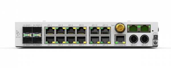
Connecting the 52/XS2 or 52/XC2 Core
The 52/XC2 and 52/XS2 cores offer a variety of ports. See below how the cores have to be connected.
Network Connection
To send the configuration to the 52/XC2 and 52/XS2 cores, see the system state and also for sending and receiving external control data, both devices have one ethernet interface ETH1. Connect the ETH1 connector to a network matching the DHD Network Specifications.
Important
Never connect the ETH1 port of a DHD Series 52 core device to a unrestricted network. This would be a major security issue.
Important
Only the ETH1 port is an ethernet port. APC-Ports are no ethernet ports. Connecting APC ports to a non-DHD-device or a network switch can cause serious damage!
On the same network connector, also an internal Dante Ultimo 4×4 Audio over IP interface is running. Thus this is only one physical connector, the Dante™ Ultimo Dante 4×4 and ETH1 port are different devices running on different interfaces. They have to be configured seperately and also have a different set of network options and IP/MAC address. The Dante 4×4 Interface is configured using Dante™ Controller. For more information on configuration of Dante devices, see Dante™ information.
Connecting modules to the APC ports
The control modules and I/O boxes have to be connected to the APC ports of the 52/XS Cores 52-18xx. It is important to connect the peripheral modules to the correct APC port.
Important
Use always shielded CAT5 or CAT6 ethernet cables (at least S/UTP, F/UTP or SF/UTP) to connect these modules to the XS core.
Important
See APC documentation for more information on APC.
In the following table you can find the assignment of the control modules, I/O boxes, DeviceLinks and TFT/Touch displays to the APC ports.
| Name of the APC port | 52-7424 | 52-1830 |
|---|---|---|
| APC 1 | Central control module (52-5614) | Central control module (52-5614) |
| APC 2 | Fader module 1 (52-5620) | Fader module 1 (52-5620) / I/O box 3 / Device Link 1) |
| APC 3 | Fader module 2 (52-5620) / I/O box 6 / DeviceLink 2) | Fader module 2 (52-5620) / I/O box 2 / Device Link 3) |
| APC 4 | I/O box 5 / DeviceLink | I/O box 1 / Device Link |
| APC 5 | I/O box 4 / DeviceLink | n. a. |
| APC 6 | I/O box 3 / DeviceLink | n. a. |
| APC 7 | I/O box 2 / DeviceLink | n. a. |
| APC 8 | I/O box 1 / DeviceLink | n. a. |
Note
Have a look at the following schematics regarding cabling for the SX2 bundles:
52-1989A Cabling Overview
52-1998A Cabling Overview
52-1999A Cabling Overview
Connecting 52-7321 MADI modules
The 52-7321 MADI module supports up to 64 channels. It is always configured to SFP 1 housing. See Fibre optical connections documentation on wiring.
Connecting 52-7391 Gigabit Audio (GA) modules
The 52-7391 Gigabit Audio (GA) module supports up to 512 channels. Gigabit Audio is a DHD proprietary audio connection protocol and only works between DHD devices. It is always configured to SFP 2 housing. See Fibre optical connections documentation on wiring.
Connecting 52-7080 Dante Brooklyn modules
The 52-7080 Dante Brooklyn Audio over IP module is connected to the internal Core extension slot (upper right corner of the back of the core). It always contains a Primary (left) and a Secondary (right) ethernet port. You can connect it to any network. See Dante™ information.
Connecting 52-7067 AES67 RAVENNA modules
The 52-7067 AES67 RAVENNA Audio over IP module is connected to the internal Core extension slot (upper right corner of the back of the core). It always contains a Primary (left) and a Secondary (right) ethernet port. You can connect it to any network. See AES67 RAVENNA Interface documentation.

