Console
On the Console page you can configure keys and TFT views.
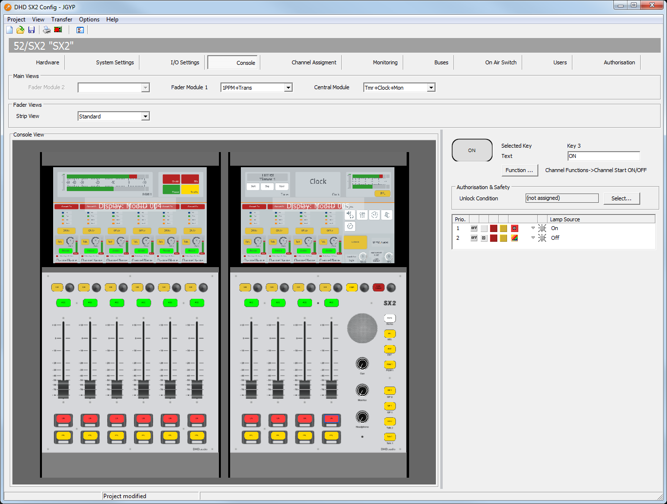
Main Views
In the Main Views Section, you can choose the central view each module is showing
Note
For more information on screen sections see SX2 - Central Module
Each module can show one of the Available Main Views as described below. Selection is done per module in the corresponding drop-down menu. Available Modules are:
Available Main Views
There are various main views for the fader and central modules available. Below you find documentation of all available views.
Tip
The available main views are designed to work together on different TFT screens in combination or standalone. Thus there are many elements redundant. Make sure to select different main views on different modules that do not contain the same sections.
Empty
This is an empty view.

Logo only
This view contains only the logo set in System Settings - Logo Replace.

Tmr+Clock+Mon
This view contains 3 sections:
- Timer: Press
Startto start the Timer andStopto stop the timer.Resetsets it back to 0. - Clock: Shows the current time. Make sure a valid NTP time server is configured for your core. See Time Server manual.
- Monitor peak meter. Shows the current Monitor level. Source Select: Tap on the peak meter once to select the source for the
Monpeak meter. The TFT display will change toPPM Source Selectpage. Select the source. TapBackonce finished.

Tmr+Clock+Trans
This view contains 3 sections:
- Timer: Press
Startto start the Timer andStopto stop the timer.Resetsets it back to 0. - Clock: Shows the current time. Make sure a valid NTP time server is configured for your core. See Time Server manual.
- State Indicators: Indicate the state of pre-configured system logics. See System Settings - TFT State Indicators.

Clock+Trans+2PPM
This view contains 4 sections:
- Clock: Shows the current time. Make sure a valid NTP time server is configured for your core. See Time Server manual.
- State Indicators: Indicate the state of pre-configured system logics. See System Settings - TFT State Indicators.
- PGM 1 Peak Meter: Shows the current level of PGM 1 bus.
- Monitor peak meter. Shows the current Monitor level. Source Select: Tap on the peak meter once to select the source for the
Monpeak meter. The TFT display will change toPPM Source Selectpage. Select the source. TapBackonce finished.

Clock+Tmr+2PPM
This view contains 4 sections:
- Clock: Shows the current time. Make sure a valid NTP time server is configured for your core. See Time Server manual.
- Timer: Press
Startto start the Timer andStopto stop the timer.Resetsets it back to 0. - PGM 1 Peak Meter: Shows the current level of PGM 1 bus.
- Monitor peak meter. Shows the current Monitor level. Source Select: Tap on the peak meter once to select the source for the
Monpeak meter. The TFT display will change toPPM Source Selectpage. Select the source. TapBackonce finished.

1PPM+Trans
This view contains 2 sections:
- PGM 1 Peak Meter: Shows the current level of PGM 1 bus.
- State Indicators: Indicate the state of pre-configured system logics. See System Settings - TFT State Indicators.

1PPM+Mon
This view contains 2 sections:
- PGM 1 Peak Meter: Shows the current level of PGM 1 bus.
- Monitor peak meter. Shows the current Monitor level. Source Select: Tap on the peak meter once to select the source for the
Monpeak meter. The TFT display will change toPPM Source Selectpage. Select the source. TapBackonce finished.

Mon+PPM+Transp
This view contains 2 sections:
- Monitor peak meter. Shows the current Monitor level. Source Select: Tap on the peak meter once to select the source for the
Monpeak meter. The TFT display will change toPPM Source Selectpage. Select the source. TapBackonce finished. - PGM 1 Peak Meter: Shows the current level of PGM 1 bus.
- State Indicators: Indicate the states of pre-configured system logics. See System Settings - TFT State Indicators.

4PPM+Transp v1
This view contains 5 sections:
- PGM 1 Peak Meter: Shows the current level of PGM 1 bus.
- PGM 2 Peak Meter: Shows the current level of PGM 2 bus.
- AUX 1 Peak Meter: Shows the current level of AUX 1 bus.
- AUX 2 Peak Meter: Shows the current level of AUX 2 bus.
- State Indicators: Indicate the state of pre-configured system logics. See System Settings - TFT State Indicators.

4PPM+Transp v2
This view contains 5 sections:
- PGM 1 Peak Meter: Shows the current level of PGM 1 bus.
- Monitor peak meter. Shows the current Monitor level. Source Select: Tap on the peak meter once to select the source for the
Monpeak meter. The TFT display will change toPPM Source Selectpage. Select the source. TapBackonce finished. - AUX 1 Peak Meter: Shows the current level of AUX 1 bus.
- AUX 2 Peak Meter: Shows the current level of AUX 2 bus.
- State Indicators: Indicate the state of pre-configured system logics. See System Settings - TFT State Indicators.

Fader Views
There are various fader views for the fader strips available. Below you find documentation of all available fader views. The selected fader view is always the same on all fader channels.
Every fader view is structured the same way and can be split into the following functional areas:

- 1:
Channel OnIndication: red when the channel is on. - 2: DSP Plugin and AUX routing indication. Visibility depends on the selected fader strip view.
EQ: Indicator is blue when EQ or SubSonic are onDyn: Indicator is green when Compressor or Limiter is on.Aux 1&Aux 2: Indicator is orange if channel is routed to the AUX bus.
- 3: Optional touch button area. Can contain bus routing or access key, depending on selected fader strip view.
- 4: An area, where the upper key and encoder functions of the hardware are labeled and mirrored. Can also be used to control the assigned functionality via touch input. See SX2 - Fader Modules.
- 5: Hidden layer channel name and On/Off state (only if Layer B is configured. See Channel Assignment).
- 6: Channel Name and channel on indication (grey/red bar)
Available Fader Views
Standard

Minimal

Minimal + ACCESS

Minimal + OffAir

PGM

PGM + AUX

Console View
In the Console View Area, you can see a preview of the console layout, TFT Displays, and keys. Also, key function configuration is done here: simply click on the key you want to edit.
Key Elements
| option | description |
|---|---|
| Number | Shows the generated number of the selected key: <name of fader module>.Key<key number on this module> |
| Function | Shows the assigned key function. To change the default key function of a key, follow these steps: 1. Select a key on the console view. 2. In the View menu, select Key Functions. The Key Functions window opens.3. In the Key Functions window select a Key Function from the list and click Select. |
| Label | Enter a name for the key. This name will be shown in the Console View and will be available for the label print feature. |
| Colors | Depending on the selected key function, you can define here, with which color the key shall light up according to the lamp source. On is the color if the function is enabled, Off if the function is in the inactive condition. For the last case, mostly the Off option is used, for example, the key does not light up. Depending on the selected key function, you find also different names in the Lamp Source column, for example Standby, Available, Busy, Owned, Layer A, Layer B or the name of the selected lamp source. You can define the colors red and yellow. You can define flashing colors for the keys. Select the check box, in the Colors area. To change the logic source for a color, select an entry in the Lamp Source column and click Source. The Logic Sources window opens. In the Logic Sources window, select a logic source from the list and click Assign. |
| Toggle Mode | Momentary - The function is enabled as long as the key is pressed.\\ Toggle - This key is stay put.\\ Timed Toggle - This key is stay put (short press) or spring return (long press). |
Central section keys
Note
Keys in the central section on the 52-5614 are always fixed in their function and can not be configured. Function details such as audio sources can be configured.
Overbridge Keys - Login, Load Default
Press the Login Key,
Press the Load Default key,
Monitoring keys - Extern, Selector, Program 1
Press the Extern key, to monitor a preconfigured audio source. This source can be any audio source, that is available in the mixing system. To set the audio source for this key, follow these steps:
- In the Consol View, select the Extern key (key 8).
- In the
Key Optionsarea, click theSelectbutton, next to theLeft Sourcebox, theAudio Sourceswindow opens. - In the
Audio Sourceswindow, select an audio source and clickAssign. - Now you can select the audio source for the right channel and drag it directly to the
Right Sourcebox.
Press the Selector key, to monitor an audio source which can be selected during operation via the TFT Touch Display. This source can be any audio source, that is available in the mixing system. To set the audio source for this key, follow these steps:
Press the Program 1 key, to monitor the Program Bus 1.
General Purpose keys - GP1, GP2
You can configure these keys as User defined Key or Potentiometer key.
User-defined:
- By right-clicking
(not assigned)in theLamp Sourcecolumn, you can either select the key itself as a source or select any source from thelogic sourceswindow. - You can use the key as a logic source in many ways, for example for the On-Air Switch or routing to GPOs.
- You can change the sequence of the three rows in the Colors area. Drag a row in the
Lamp Sourcecolumn to its new priority place. - The LED with higher priority lights up if its lamp source is active; two colors can't light up at the same time!
- The LEDs of the keys can also be used to show a condition without having assigned a key function. This is useful for signalization via GPIs.
Potentiometer:
- In the
Potentiometerlist you can choose from virtual potentiometers, which can be assigned to an encoder in your central module by pressing this key. - In the
Encoderlist you can choose the encoder to which the virtual potentiometer will be assigned. (F1=upper encoder, F2=lower encoder)
All available virtual potentiometers and their function are shown in the following table:
| potentiometer | function |
|---|---|
| Monitor 2 | set volume for signal “Monitor 2” |
| HP 2 | set volume for signal “HP 2” |
| Monitor 3 | set volume for signal “Monitor 3” |
| Monitor 4 | set volume for signal “Monitor 4” |
| CUESPLIT | set the ratio between the PFL signal and the monitoring signal |
| CUE/TB | set volume for the speaker in the central module |
| AUX 1 | set volume for bus “AUX1”, Aux 1 Master settings are also available via AUX Master view on the TFT Touch screen |
| AUX 2 | set volume for bus “AUX 2”, Aux 2 Master settings are also available via AUX Master view on the TFT Touch screen |
Talk Keys - Talk 1, Talk 2
You can configure these keys only as User Defined Key.
User-defined:
- By right-clicking
(not assigned)in theLamp Sourcecolumn, you can either select the key itself as a source or select any source from thelogic sourceswindow. - You can use the key as a logic source in many ways, for example for the On-Air Switch or Talkback.
- You can change the sequence of the three rows in the
Colorsarea. Drag a row in theLamp Sourcecolumn to its new priority place. - The LED with higher priority lights up if its lamp source is active; two colors can't light up at the same time!
- The LEDs of the keys can also be used to show a condition without having assigned a key function. This is useful for signalization via GPIs.
Fader Keys
You can choose the key function of all fader related keys per channel. SX2 has 4 fader related keys: 2 below and 2 above the fader.
The fader keys above the fader are labeled within the associated TFT section (See Fader Modules for more Information).
The fader keys below the fader are labeled using the delivered label stickers (See Fader Modules for more Information).
Note
Fader related keys have always the same key function for all channels.
To configure the Key function follow these steps:
- Click the fader key you want to configure. On the right-hand side, the key configuration options open.
- Click
Functionto select the designated key function. See the list of available Key functions below. - Label the key using the
Textfield. On the 2 keys above the fader, this value will be used on the TFT, too. - (optional) Some key functions require a
Toggle Modesetting:- If
momentaryis selected, the key will only be active when it is pressed. - If
Toggleis selected, a first press will turn the key function on. The key will be turned off when the key is pressed again. - If
Timed Toggleis selected, the keys operation mode will depend on the time duration it is pressed. If the key is pressed short, it is toggled. A short press again will release the key. If you press and hold the key, the key will act as momentary.
- In the
lamp sourcesection, all states can be configured with a matching color.
Available Key Functions
(No Function)
| option or sub-function | selection | description |
|---|---|---|
| • no function. |
Access Functions
| option or sub-function | selection | description |
|---|---|---|
| Access | • The console will be set to access mode for this particular channel. View on the central module will change and e.g. DSP parameters can be set. |
Channel Functions
| option or sub-function | selection | description |
|---|---|---|
| Channel ON | • The channel is switched on. | |
| Channel Off | • The channel is switched off. | |
| Channel ON/OFF | • The channel is toggled on and off using the same key. | |
| Channel Start ON | • The channel is switched on: Sets the channel and motor fader to 0 dB. Note The motor fader requires some time to get to the appropriate position. The audio signal is not affected, though! It is switched to 0 dB or -∞ dB immediately after pressing the key. |
|
| Channel Start OFF | • The channel is switched off: Sets the channel and motor fader to -∞ dB. Note The motor fader requires some time to get to the appropriate position. The audio signal is not affected, though! It is switched to 0 dB or -∞ dB immediately after pressing the key. |
|
| Channel Start ON/OFF | • By pressing the key and the function is not active, the channel is switched ON: Sets the channel and motor fader to 0 dB. After pressing the key again if the channel is already on by fader start, the channel and motor fader are set to -∞ dB. Note The motor fader requires some time to get to the appropriate position. The audio signal is not affected, though! It is switched to 0 dB or -∞ dB immediately after pressing the key. |
|
| Layer | • Toggling between Layer A and Layer B or setting a layer directly for only this channel. |
Bus Functions
| option or sub-function | selection | description |
|---|---|---|
| Program Bus | • Routes the signal to the internal Program Bus. |
|
| PFL | • Routes the signal to the PFL bus. | |
| Momentary | • The function is enabled as long as the key is pressed. | |
| Toggle | • This key is stay put. | |
| Timed Toggle | • This key is stay put (short press) or spring return (long press). | |
| Off Air | • Routes the signal to the internal Off Air bus. |
Clean Feed Functions
| Talk CF | • Activates the logic source CF Talk <Name of Input> if a fader channel with enabled clean feed is routed to a fader. • The created logic source can also be used in any other location of the system. |
|
| Momentary | • Function is enabled as long as the key is pressed. | |
| Toggle | • Key is stay put. | |
| Timed Toggle | • Key is stay put (short press) or spring return (long press). |
Fader Functions
| option or sub-function | selection | description |
|---|---|---|
| Fader Function | • Creates a logic source that can be universally used. • An application is, for example, talk button for clean feeds (instead of talk function described above). |
|
| Momentary | • This function is enabled as long as the key is pressed. | |
| Toggle | • Key is stay put. | |
| Timed Toggle | • Key is stay put (short press) or spring return (long press). |