Maintenance Window - Servicing Modules
Overview
The central part of each DHD system is the DSP unit. This can either be operated as stand-alone version (e.g., as a router) or is connected via CAN bus (RM4200D) or Ethernet (Series 52) to one or more operating devices.
You can operate several DHD systems together, for example in several studios that are linked via one central router. To simplify the configuration, you can manage routers, operating panels and other devices in one Toolbox5 project. The DSP frames in the studios are linked to the router via MADI and Ethernet, to exchange audio and controlling signals.
Important
Only one CAN bus is allowed per RM4200D DSP Frame. Therefore, it is not possible to operate several RM4200 DSP Frames on the same CAN bus.
There are no limitations for Series 52 devices, because of the Ethernet structure.
Connecting the Software to the Devices
Using the Maintenance software, you can connect the PC with the devices via Ethernet and TCP/IP. To some modules or systems, a connection can also be set up via the serial port. If possible, you should use Ethernet though, since the transfer speed is clearly higher.
In the device list, all devices are shown that are connected with the Toolbox5 PC. This includes the devices connected manually via serial port or by entering the IP address as well as devices registered automatically via UDP.
The automatic registration works as follows:
Every device transmits automatically a UDP broadcast message once per second via Ethernet that contains the following data:
- Project ID
- Device ID
- Hardware name of the device
- Name of the device
- IP Address
- Serial Number
Important
If the PC with the Maintenance software is located in a different network segment than the device, the UDP broadcast messages may not be transferred between the segments. In this case, the automatic registration of devices does not work!
To solve this problem, the transport of UDP messages must be enabled by the network administrator. This is mostly done for certain Ethernet MAC addresses.
DHD has reserved the MAC address sector 00:0A:63:xx:xx:xx for its products. The last three bytes xx:xx:xx of the MAC address are assigned by DHD during production for every Communication Controller subsequently. At least one Communication Controller must be contained in every device. The MAC address set during production can not be changed later on! Therefore, apart from the identification for the data transfer in a network, it is also used to assign the license codes. (See also Enter License)
Important
The Maintenance software was developed for Windows XP, but it runs under different versions of the Windows operating system. A known bug of Windows NT prevents the reception of UDP broadcast messages. Therefore, the automatic registration does not work, even if the Maintenance PC and the devices are located in the same network segment. In this case, the devices must be addressed manually via their IP address. (See also Network Config)
Please find further details on the protocols UDP and TCP/IP in the standard literature on computer networks or ask your system administrator.
Connecting over Wide Area Networks
DHD systems use the TCP/IP protocol for communication of the DSP frames among each other and with the Maintenance PC. In theory, DHD systems could be remote controlled via WAN if they also support TCP/IP. Practically, this does not always work correctly. The reasons are the following:
- Data throughput and latency are often unpredictable in WANs and can change suddenly. This is especially true, if the connection is set up via the open Internet and not via a corporate network.
- In contrast with a PC, a DHD device is an embedded system, which can also communicate via TCP/IP. But is it not as flexible and tolerant with errors as the PC. In a local network (LAN) with stable conditions, this is not a problem - communication will work without problems. If the communication is done via WAN though, under certain condition, data can get lost and cause unwanted problems.
Therefore, you should avoid to remote control DHD systems directly via WAN connection.
Warning
Especially, do not try to update the firmware via a WAN connection!
If you have to maintain a remote system anyway, use a remote control software like, for example PC Anywhere, Timbuktu Pro or VNC. Use this software to remote control the PC that is located on a local network with the remote system.
In addition, keep the following in mind when working with WAN connections:
- The less additional traffic is on the line, the more stable is the data transfer.
- If you have the choice, the corporate network or even a special dedicated line is mostly better than the Internet.
- It might be helpful to dial in a remote PC directly (e.g., via ISDN) than to use a computer network.
- Please stick to the usual rules for tunneling internal data traffic over public networks (VPN, Access protection, etc.). Ask your system administrator about it.
Firmware State
To read out the most important values and states of a 52/RM4200D DSP Frame or a 52/XR MADI Router, select the device in the left-handed list and afterwards click on Firmware in the main window.
Explanation of the shown values:
| Value | Description |
|---|---|
| Version | The currently installed firmware version. |
| Serial Number Device | In the devices of the Series 52, the Serial Number Device is stored on the backplane. In 52/RM4200D DSP Frames the serial number of the RM420-852/853 Communication Controller is used as Serial Number Device. This serial number is used to create licenses for the respective device on the part of DHD. If you want to purchase licenses later on, please give this number to us. |
Serial Number <Communication Controller> | The serial number of the communication controller module. (Communication Controller = 52/RM4200D: RM420-852 or RM420-853; 52/XR: 52-6850 or 52-6851) |
| MAC-Address | The MAC address of the communication controller module. The first 3 bytes (00:0A:63) are always identical and indicate that it is a DHD device. |
| Hour Meter | Operational hour meter of the controller module; 0 hours of operation on delivery. |
| Firmware uptime | Current runtime since last start up. |
| CyclTime | This value is an indication for the load of the firmware. Evaluation is only done on the part of DHD. |
| Running as | A 52/XR MADI Router could contain two communication controller modules 52-6850. Always one of these modules is running as MASTER and the other one is the SLAVE. Only the MASTER is in use. If the MASTER module drops out, the SLAVE module takes over and becomes MASTER. In case of the 52/RM4200D DSP Frame or if only one communication controller module 52-6850 or 52-6851 is installed in a 52/XR, the respective controller is always operated in MASTER mode. |
| Sync Module | In 52/XR frames this number indicates to which synchronisation module (1 = slot 1, 2 = slot 20) the following information (system frequency and sync source) are related to. In case of the 52/RM4200D DSP Frame this value is always “1”. |
| System frequency | Currently used synchronisation frequency. |
| Sync Source | Indicates which of the configured synchronisation sources is used at the moment. |
| 1.2 V, 1.3 V, 2.5 V, 3.3 V, 5.0 V | Current operational voltage values. |
| Temp | Operation temperature, measured on the communication controller module. |
| PSU 1-4 (52/RM4200D DSP Frame only!) | Here you can find the module types of the installed 5 V and 24 V power supply units. |
| AD e, AD f (52/RM4200D DSP Frame only!) | These values are only useful for DHD. |
| (0.0.0.0) | This entry stands for an internal process, that is needed to create the following entries. |
<Controller Modules> | A list of all controllers that are connected to the communication controller (possible types: RM420-851, 52-4050, 52-4015). Next to the controller name you can find the serial number (RM420-851) or the IP address (52-4050, 52-4015). The controllers are listed in the order they have logged on. In the right-handed column you can find a 3 digit number that represents the module ID. On part of DHD this number can be translated to get information on the position of the controller in the system. Following the uptime, the currently installed firmware version on the controller and may be the last reset action (External Reset = device on, System Reset = manual restart of the operating software, Watchdog Reset = internally triggered restart, forced by the system) are listed. |
| Slot 1 … n | Every module of the system is shown with its module name, revision, serial number and the slot number where the module is located. The revision and the serial number of the 52/XR MADI Router modules are not shown. Moreover, it is possible to click on the entries of 52/RM4200D DSP Frame audio and/or GPIO modules to read out the commissioning protocol of the modules. |
Additionally, also other information can be listed here (e.g., powerfail).
Weblink
Please see the 52/MB MADI Breakout System and 52/CR Compact Router manuals to learn more about the system state of these devices.
• 52/MB manual > System State
• 52/CR manual > System State
File Menu
Close
Closes the Maintenance software. Since you can not save or edit files in the software, you do not have to confirm before quitting the program.
Device Menu
Reconnect
The Reconnect command interrupts the TCP/IP connection between the Maintenance PC and the selected device and opens it again. This way, the current settings of the device are read out automatically.
Tip
For certain functions, transferring the commands can take quite a while, longer than the Refresh process of the Maintenance Window. In this case, the old values are shown although the new one are available to the hardware already. Use the Reconnect function to check the settings if in doubt.
Network Config
With this command, you open the Network Config window of the Maintenance software. In this window you can change the IP settings of the device.
After selecting a system by right-clicking on it in the device list in the Maintenance Window, a contextual menu opens that allows access to the IP settings using the command Network Config.

There are two ways to change the IP configuration of a DHD system:
(a) You see the appropriate device in the list on the left of the Maintenance Window.
(b) You do not see the appropriate device in the list on the left of the Maintenance Window.
You see the device in the List (a)
- Right-click on the device name in the list.
- A contextual menu appears. Select the command
Network Config - A window opens showing the IP configuration of the device.
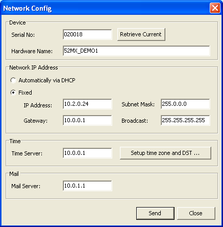
In the Network Config window, you can change the current IP configuration of a certain device.
Serial No
The device the network settings of which are shown, is always represented by its Serial No. This serial number is unambiguous and valid for only one controller. The field is used to read out settings of devices that are located in a different network segment. Find more details on this in the following section “You do not see the device in the list (b)”.
Hardware Name
Every Series 52 system can be assigned a Hardware Name for better identification of the system. This name helps to identify the device in the network. You can choose any name, it can be up to 30 digits long but may not contain spaces. Special characters that are not allowed, can not be entered. In the maintenance software DHD Maintenance (DHDMT) only the first 10 digits of the hardware name are shown.
Automatically via DHCP
If a DHCP server is located in the network that manages the IP configuration of the selected device, select the option Automatically via DHCP.
Fixed - Fixed IP setting
If you have no access to a DHCP server or want to adjust the IP configuration manually, first select Fixed and then enter the appropriate values (IP-Address, Subnet Mask, Gateway, Broadcast) into the appropriate boxes.
Important
In case of question concerning the parameter settings, ask your IT department or your system administrator.
Time Server
Series 52 systems have an internal system time that can be synchronised using a NTP Time Server. To have this done, enter the IP address of your NTP Time Server in the Time Server box.
Depending on your chosen time server you may need to enter some further settings. Click Setup time zone and DST to be able to enter a general time zone offset and if necessary the settings for the daylight saving time.
Tip
A standard Windows PC can be used as a NTP time server, see Configure Windows as a NTP time server
Mail Server
This box has no function and needs not to be filled.
If you have changed the existing settings, they have to be transferred into the device. For this, click Send. If you want to aboard possible changes and close the Network Config window, click Close.
You do not see the device in the List (b)
- In the
Devicemenu, clickNetwork Config. - The
Network Configwindow opens with all boxes empty. - Enter the serial number of the device in the
Serial Nobox. Then clickRetrieve Current.
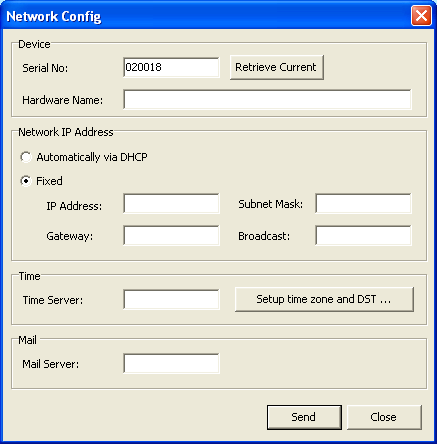
This way, a request is sent into the network searching for devices over the borders of the subnet. If the device is located outside the subnet of the PC, it will answer anyway and transfer the current IP settings. These are then shown in the Network Config window and can be changed there.
Changing the data is carried out exactly as described in “You see the device in the List (a)”. Changed data are finally transferred to the device by clicking Send.
Nevertheless, if the device is not reacting, communication could be blocked by certain IP settings. In this case it is recommended to adjust the IP settings of the PC to the ones of the device. To do this, temporarily change the IP address of the PC to the one valid for the device (see IP basic setting).
There is no Communication possible with the device
If, despite all efforts, the device is not reacting although there is a physical connection to your network, the communication might be blocked due to the current security settings in the network. In this case, check which measures for a higher network security may be dropped (e.g., firewalls, router, managed switches, …).
For solving the connection problems, contact the responsible IT department and check which of the measures described in the network specification have to be done to establish a communication between PC and DHD system.
Alternatively, you can use the USB port for communicating instead of the network connection.
Enter License
Using this command, you can enter the license codes without the software is not working. There are license codes for the software operation and in addition codes for enabling the Enhanced DSP Functions. The last, enable the optional processing functions and must be ordered separately.
Note
An invalid license code allows unlimited operation (except the enhanced DSP functions) of a device for 600 operating hours, this corresponds to 25 days non-stop operation. After that, the message License invalid is shown in the module display. Apart from this message, the mixer operation is still unlimited (except the enhanced DSP functions). After 800 hours of operation without license, the system is interrupted by a random reset approx. once per hour. The enhanced DSP functions are disabled without a valid license code, the signals are only bypassed in the DSP.
Generally, only one license code is necessary for operating one DHD system. Each system has its own license code based on the serial number of the device. You find the serial number under Serial Number Device in the firmware section after selecting a device.
Important
You can also get the license for a Communication Controller module. When exchanging this module, you might need a new license code that you can request from DHD.
In most cases, DHD products are delivered with a temporary license code (valid until…). As soon as the system has become the property of the customer, DHD sends the permanent license code by e-mail. When you have received the license code, copy it by pressing Ctrl+C. Then select the desired device in the device list and select Enter License. Then, insert the code into the box by pressing Ctrl+V and confirm by clicking OK. The code is transferred to the device.
Check whether the license code was accepted. To do this, in the main menu, click License Information. If you read Firmware License: unlimited valid or for temporary licenses valid until with a new date, the transfer was successful. The same applies for enabling the enhanced DSP functions at Enhanced Processing.
A faulty license code is ignored!
System Status
Save To File
In the Device menu, select System Status - Save to File, to save the currently read out status of the device. A file named System_Status_<Project ID>_<Hardware Name>_<Date>_<Time>.tgz is created.
If you want to read out the saved content, you first have to unzip it using a ZIP-decompressor. The result is a file with the same name but the extension .tar. Now, open this file using a RAR-decompressor. Finally, some files with the extension .xml emerge as well as some files necessary to show the XML files. You can view the XML files in a browser (e.g., the Microsoft Internet Explorer). For this, open index.xml. The view is the same as if you had selected the device in the device list. Then, you can view the other pages like in the Maintenance software.
Send by Mail
This function creates in a first step the same zipped file like the command Save to File. (See Save to File)
Then, you instantly can send this file per e-mail to DHD support. For this, it is necessary to have Microsoft Outlook installed on the PC and to set up a user account. In this case, a new mail window is opened automatically and the files created are attached. Only click Send and the e-mail is transferred to the DHD support team.
Restore Snapshots
The function Restore Snapshots is only useful in conjunction with the firmware version 6.3.x. Due to the fact that the file structure of the snapshots changed in the firmware version 6.4.x, this function is not working with the firmware version 6.4.x.
Since TB5 v7.4.X this function works again.
With the aid of this function it is possible to transfer one or more mixer and channel snapshots from the PC to the console. (Use the function Save to File to save all mixer and channel snapshots of a device.)
Mixer 1 to 4
In the Toolbox5 software, you can create several virtual mixers for a mixing device. Select a mixer that you want to save in the snapshot. If you did not create virtual mixers, save the snapshots in Mixer 1.Also
Save Snapshot 0
This command copies the current content of the parameter RAM of a mixing device to the Mixer Snapshot 0 storage area in the flash storage of the Communication Controller. This way, the settings are kept also after switching off the device and can be used as default setup after a reset. Snapshot 0 can also be loaded via the console like all other snapshots.
Note
The Default Snapshot 0 can only be saved using this command. There is no option to do this at the console!
First you have to select the desired device to trigger the command. After that, a security confirmation message Save current Parameter settings? is shown. After confirming with Yes the settings are copied.
Important
It is vital to choose the command Save Snapshot 0 after every setting into operation or after changing the configuration of the fader channels of a mixing device! Only this way, the system can restart using parameters that make sense after a reset, especially for the settings of Analog Gain, Phantom power, Fader assignment and Bus assignment!
Clear Parameter Memory
This function sets all DSP parameters of all channels to the default values.
Important
Resetting the parameters influences the audio processing of all channels. Make sure that it does not adversely affect important signals.
Calibrate Display
With this function, you start the calibration procedure of a TFT display. In general, it is not necessary to use this function since the TFT displays are calibrated before shipping by DHD.
This process is for adjusting the XY-extension of the shown image on a TFT display. This way, you make sure that the touch-sensitive areas (buttons) are complying with the display. The view angle is preset and can not be changed.
After starting the function Calibrate Display, on the selected TFT display, four crosses appear. Select them one after the other exactly using a pointed object. The output of the monitor is adjusted and calibration is finished.
If the respective TFT display is connected to an 52/MX console, it is not shown in the device list of the Maintenance Window. Disconnect the TFT display from the console and connect it directly to the DHD network. Then you can use the function as described above.
Firmware Reset
Select Firmware Reset to restart the firmware of the selected device.
You find the Firmware Reset command also in the contextual menu by right-clicking on a device in the device list.
Warning
A firmware reset temporarily interrupts the audio processing of the system. Make a firmware reset only if you are sure that it does not influence important signals.
System Reboot
Select System Reboot to restart the boot loader of the selected device.
You find the System Reboot command also in the contextual menu by right-clicking on a device in the device list.
Warning
A system reboot temporarily interrupts the audio processing of the system. Make a system reboot only if you are sure that it does not influence important signals.
Factory Test
This function can be used to check every single element of the fader and control modules of a 52/MX mixing console.
Note
This function is not useful to check a 52/RM4200D desk.
Before a device is shipped, the functionality of all elements is tested by DHD. If you think that your console could have a hardware problem (e.g., a key is not working), you can clarify this with the aid of this function.
Before you use this option, you should transfer an empty configuration to the device. This makes the results more clear, because there will be no overlapping with the configured functions. Therefore, add a new device to your Toolbox5 project and transfer this empty configuration into the device.
Testable with this function are faders, keys, encoders, potentiometers, OLED displays and LEDs. The functionality of the TFT displays can not be checked with the factory test. Use the function Calibrate Display to set up TFT displays and to assure their operational readiness.
Keys
By pressing a key it will light up for approx. 3 to 5 seconds. Independently if you press the same or several keys after each other, the colour of the light will change automatically depending on possible states of the key (e.g., yellow-red-green, yellow-red-yellow or green-red-green). Additionally, pressing the keys of fader modules sets the fader values to defined positions (approx. +10 dB, -6 dB, -25 dB and -oo). Of course the fader itself will only move if it is a motor fader.
Faders
The current fader position is shown in the OLED display of this fader module as a digital value (typical values: min.=0005, max.=4093).
The modules 52-4240 and 52-4241 have six LEDs next to the fader (PGM 1/2, AUX 1-4). In the factory test mode, these LEDs also represent the fader value, but not that exactly as it is done in the OLED displays. The LEDs are standing for several bits (PGM 1 = 2^6 = 64, PGM 2 = 128, AUX 1 = 256 and so on). The LEDs of the modules 52-4230 and 52-4231 do not represent a bit pattern, they are driven as a running light.
If the console is grounded correctly, you will see a T in the OLED display when touching the fader. Also moving the fader is recognized as a touch and will cause a T in the display.
Encoders
In the OLED displays next to the encoders a value between 00000 and 65535 is shown that can be increased and decreased using the encoder. On pressing the encoder, a key of the same module lights up (pressing several times changes the colour).
Potentiometers
In the OLED displays next to the potentiometers a value between 0001 and 4093 is shown that can be increased and decreased using the potentiometer.
Protocol Menu
In this menu you can define the way the display in the protocol window of the Maintenance software works. In the section Show Protocol Window you learn how to open the protocol window.
Enable Protocol
If click on the Enable Protocol command, the protocol window shows all commands that are transferred in the network.
Without knowing further details about the protocol, you can also simply press the appropriate key, especially for key functions. The corresponding command is then shown in the protocol. You can then send it manually or use it in a script.
Use these functions mainly for temporary maintenance. For longer protocol sessions, use the DHD Communication Server (DHDCS).
The Enable Protocol command can be enabled by pressing F4, if a system is selected in the device list. The amount of data shown in the protocol window increases massively, if the protocol function is enabled. At the same time, also the size of the log file is increasing.
Show Protocol Window
Show Protocol Window opens the protocol window. In this window, you can track all sent UDP and TCP/IP messages in the network. Select the Enable Protocol check box to start the recording of the protocol.
If you want to see the messages of the device selected in the list only, select the Filter foreign UDP blocks check box. Click Clear Window to delete all messages in the protocol window. The log file is not affected by this.
In the boxes TCP Block and UDP Block you can enter a TCP/IP or UDP command directly and transfer it into the network, by clicking Send.
All sent commands are saved and available in drop-down menus at the boxes TCP Block and UDP Block to be sent again. If you want to delete all saved commands, click Clear History.
Show Log File
Use this command, to open a text file. This is actually the log file of the DHD Communication Server (DHDCS).
Changes concerning these log files can only be done using the DHDCS. Start the DHDCS or maximise it by double-clicking on the icon in the icon tray. In the Logging/Options menu, on the General tab in the box Log file directory, you can define where the file is to be saved. On the Filter Settings tab, you can define which data are recorded.
The log file can also be opened by pressing Ctrl+E on your keyboard.
Update
Update Firmware
Every device is equipped with the most up-to-date firmware at the time of delivery. Because the software is developed constantly, after a certain time, a newer version might be available than the one in your system. Ask your DHD vendor for the current state of the firmware for your device.
If a newer version is available, you first have to consider whether an update makes sense to you.
Tip
Update the firmware only if
- you need new functions that are not yet supported by your version,
- the new version fixes bugs that affect your system or
- your DHD vendor or DHD recommend an update.
Normally,the firmware of a working system does not have to be updated.
If you want to update the firmware, first find out the firmware version on your system.
The processing or the shown dialogs of the Maintenance software can vary depending on the device type. The following procedure refers to the firmware update of an 52/MB MADI Breakout System of the Series 52.
1. In the device list of the maintenance software, select the device of which you want to update the firmware.
2. After that, in the main section click on the link System State. A list of system parameters is shown. In the line Version you find facts on the currently running firmware version (see as indicated).

3. A firmware update is supplied as a file. Firmware updates of DHD devices are numbered as follows:
MB-CR_06-01-01.fw6
The shortcut MB-CR_06 describes the firmware version of the device. The second number (here: 01) relates to the major version of the firmware. The third number reflects the minor version of the firmware (here: 01). The fourth number must always be 01 and indicates that this is an official version. This number is not shown explicitly in the file name. Every firmware file has the file extension .fw6.
In the Update menu select Update Firmware and open the update file. The validity is tested and you are asked to confirm and start the update or cancel the procedure if necessary.

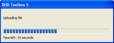
4. The update starts after you click Yes. The process is indicated by a progress bar and takes only a few seconds.

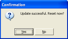
5. After the successful update, you are asked to restart the system. The new firmware is accepted by the system only after this system reboot.

Important
A system reboot temporarily interrupts the audio processing of the system. Reboot only if you are sure that it does not influence important signals.
You can postpone the system reboot, but keep in mind that the system runs on the old firmware version until the restart is made.
Update Kernel
Every device is equipped with the most up-to-date kernel at the time of delivery. Because the software is developed constantly, after a certain time, a newer version might be available than the one in your system. Ask your DHD vendor for the current state of the kernel for your device.
If a new version is available, you first have to consider whether an update makes sense to you.
Tip
Update the kernel only if
- you need new functions that are not yet supported by your version,
- the new version fixes bugs that affect your system or
- your DHD vendor or DHD recommend an update.
Normally, the kernel of a working system does not have to be updated.
If you want to update a kernel, first find out the kernel version on your system.
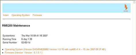
The processing or the shown dialogs of the Maintenance software can vary depending on the device type. The following procedure refers to the kernel update of an 52/XR MADI Router of the Series 52.
1. In the device List of the maintenance software, select the device of which you want to update the kernel.
2. In the main section, a list of system parameters is shown. In the line Operating System you find facts on the currently available kernel version.
3. A kernel update is supplied as a file. Kernel updates for a DHD device are named according to the following scheme:
52_01-01-15.img
The shortcut 52_01 describes the official kernel version for the device. The second number (here 01) names the major version of the kernel. The third number corresponds with the minor version of the kernel (here 15). The fourth number must always be 00, because it indicates that this is the official version. The number is not explicitly quoted in the file name. Every kernel file of the device has the extension .img.
In the Update menu select Update Kernel and open the update file. The validity is tested and you are asked to confirm and start the update or cancel the procedure if necessary.
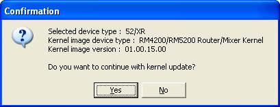
4. The update starts after you click Yes. The process is indicated by a progress bar and takes only a few seconds.
5. After the successful update, you are asked to restart the system. The new kernel is accepted by the system only after this restart.
Important
A reset temporarily interrupts the audio processing of the system. Reset the system only if you are sure that it does not influence important signals.
You can postpone the system reset, but keep in mind that the system runs on the old kernel version until the reset is made.
Typical Applications of the Maintenance Window
In the following section, the typical applications of the Maintenance Window are shortly described.
Updating the Firmware
First, read out the version of the firmware currently loaded. Compare it with the current firmware version recommended by DHD. If you have to update the firmware, proceed as described in the Update Firmware section.
Updating the Kernel
First, read out the version of the kernel currently loaded. Compare it with the current kernel version recommended by DHD. If you have to update the kernel, proceed as described in the Kernel Update section.
Storing Mixer Snapshots
Mixer snapshots save the overall condition of a mixing device. Using the Maintenance Window, you can save the Snapshot 0 that can be loaded to the console by the user. Snapshot 0 is the default setup that is loaded after a system reset. This setup can only be saved in the Maintenance Window. From the console it can be loaded but not saved. (See Mixer 1 bis 4)
Setting up Replacement Modules
If you change a Communication Controller module in a device, you might have to update the firmware of the controller (see Update Firmware). The same applies for the kernel of the controller (see Update Kernel). Further on, you may have to request new license codes from DHD after exchanging the module (see Enter License).
When exchanging other modules, these update processes are not necessary, because they get the software in the device automatically.
If it makes sense, you can also replace a newer firmware version by an older one. This may be helpful if you want to insert a new module in a device with older firmware, whereas the module has been shipped with new firmware. If in doubt, ask your DHD vendor or the DHD support prior to any downdates!
Reading out and Changing the License Code
Check the current license information for the device. To do this, in the main menu click Firmware and in the next view on License Information.
You need a license code for operating the system and optionally for the Enhanced DSP Functions. If you want to enter a new license code, use the command Enter License. (See Enter License)