Program Menus
In this section of the manual, the menus and the commands of the Toolbox5 software are described.
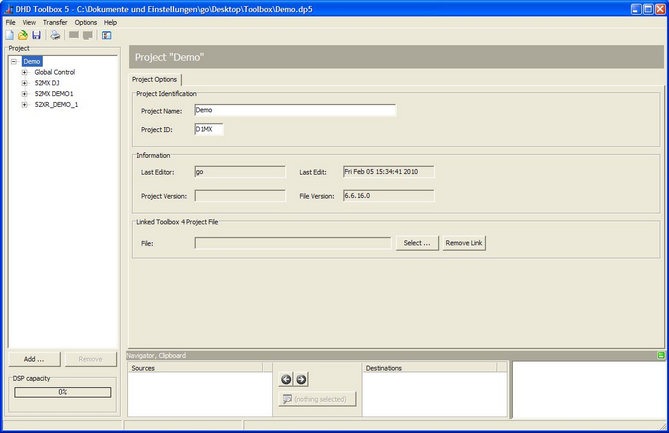
The main window of Toolbox5:
File Menu
New Project
A new project file is created and its Project ID is generated by a random generator. The project is empty and contains no devices.
This command can also be executed by clicking ![]() in the toolbar.
in the toolbar.
If a project file is already open, it can be saved before creating the new file.
Note
In Toolbox5, only one project file can be shown at the same time. It is possible to open the Toolbox5 software several times on a PC to be able to edit several projects at the same time.
Open Project
An already existing project file is opened.
You can execute this command also by clicking ![]() in the toolbar or by pressing
in the toolbar or by pressing Ctrl+O.
If a project file is open already, it can be saved before opening the new file.
Note
If you open a project that was saved with an older version of Toolbox5, a backup file is automatically created. The file is named Backup_TB5Version_6-x-x_<original file name>.ddp and is located in the same folder like the original project file.
Save Project
The current project is saved.
The command can also be executed by clicking ![]() in the toolbar or by pressing
in the toolbar or by pressing Ctrl+S on the keyboard.
Save Project As
The current project file is saved with a different name. The program suggests the current name in the Save dialog box. The new project file is available for further configuration directly after saving, the original file is closed.
Compared to the function Save Copy of Project File as you are automatically working with the new created file after saving.
Save Copy of Project File as
The current project file is saved under a different name. The program suggests the current name in the Save dialog box.
Compared to the function Save Project as, after saving you are still working with the original file and the new created file is only saved.
Tip
Use this command to save intermediate states of a project file as backup.
Import
In this section import options of Toolbox5 are explained.
Replace Device from File
It is possible to save the configuration of each device separately in a file. (See Export Device to File) Using the command Replace Device from File the user can select a device file (extension .dd5) and overwrite a device in the project with its contents.
This function is only available if a device is selected in the project tree. Otherwise, it is inactive.
Warning
The configuration of a device that is already available in the project is overwritten by this command and can not be restored. Therefore, the program opens a confirmation message before you can select a device file. If you confirm the file selection in the Open dialog box, the configuration currently available in the device is completely overwritten! Therefore, if in doubt, previously save the old configuration of the device using the command Export Device to File.
Using this command, you can transfer an already existing device configuration from one project to another. To do so, follow these steps:
- Save the device configuration that is already available in the appropriate project. There, select the desired device from the project tree and save the configuration to a file using the
Export Device to Filecommand. - In the new project, create an empty device. To do this, click
Addunder the project tree. - Select the new device and click
Replace Device from File. Select the file you created in the first step. Now you have copied the configuration of a device from the existing into a new project.
Important
When copying device configurations, pay attention to global functions that may be defined already. The available values for global logics and global potentiometers may be overwritten with the information from the device file (depending on the actual configuration).
Add TFT config from File
It is possible to transfer the configured TFT views from one mixing device to another, even if the devices are located in different Toolbox5 projects. (See Export TFT config to File) With the command Add TFT config from File the user can select a TFT config file (extension .dt5) and add the saved views to the TFT views of the device selected in the project tree. Already existing TFT views are not overwritten.
This function is only available if a device is selected in the project tree. Otherwise, the option is inactive.
Using this command, single or several TFT views can be transferred at the same time from one device to another. To do this, follow these steps:
- Save the already existing TFT views of the corresponding device. To do this, select the desired device in the project tree and save its TFT view configuration using the command
Export TFT config to File. - Select the device you want to transfer the TFT views to and select the command
Add TFT config from File. Select the file you created in the first step. You have now copied the TFT views from one device to another.
Important
After copying the TFT views, remember the links between display elements and buttons with functions. To use the the TFT views correctly, the functions of the display elements have to be configured for the new device.
Example: You have loaded a TFT view that shows filter settings on a channel. At least one EQ must be configured as DSP function on this channel.
Export
In this section export options of Toolbox5 are explained.
Export Device to File
This command saves the configuration of a device as file with the extension .dd5. Any name can be chosen for the file.
This function is only available if a device is selected in the project tree. Otherwise, it is inactive.
Export TFT config to File
This command saves the TFT views of a device as a file with the extension .dt5. You can choose any file name.
This function is only available if a device is selected in the project tree. Otherwise, this option is inactive.
Save Project as XML
This command saves the settings of the whole project as a XML structured file with the extension .xp5. Any name can be chosen for the file.
The information in this XML code is especially of interest to developers of third party software applications and hardware that should deal with the configured data of the Toolbox5 project.
Export AudioIDs/LogicIDs
This command saves the audio and logic IDs of a device as file with the extension .dpx. Any name can be chosen for the file.
The content of this file is useful if you want third party devices to communicate with the DHD system by an external protocol. Because the audio and logic IDs are assigned dynamically in Toolbox5, it is necessary to take a look at this list. Therefore, open the file with a text editor.
History
Using the History function in the File menu of Toolbox5, you can log modifications of the configuration. This way, you can later reproduce, which user made which modifications of the system at which time.

In the File menu click History; the Project History window opens. On the Project Message History tab, in the History Log area, the single entries are shown with date and time, as well as the login name of the user (Microsoft Windows Login) who created the entry. Toolbox5 itself logs some processes, for example when and by who a configuration was originally created. Other changes that seem important to you can be inserted manually.
To do this, select the New Message tab, type the new message and click Save to log the text in the history. Click Clear to delete the whole text that is entered in the Enter Message box.
To show a message, on the Project Message History tab, select an entry in the History Log list. The text is then shown in the Message box.
Note
A history entry can not be changed or deleted, once the entry was saved.
Using this command, different printouts can be arranged.
You can also execute this command by clicking in the toolbar.
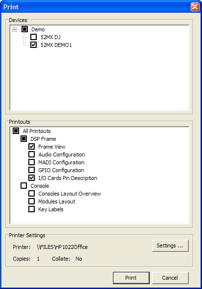
In the Print dialog, you can choose in the Devices area, which device in the project the printout is intended for. Select the project root (indicated by the project name) to include all devices or select just single devices.
In the Printouts area you can select, which parts of the documentation of the selected devices are to be printed.
The option All Printouts includes the complete documentation of the selected devices. Alternatively, you can also print all printouts of the DSP frames and/or all printouts of the console view as well as single parts of the documentation. You can select the following print sections:
Frame View: View of the DSP frame with selected board configuration.Audio Configuration: List of audio configurations with corresponding labels, slot- and port numbers and further options. To keep the list compact, no MADI modules are included.MADI Configuration: List of MADI configurations with corresponding labels, slot- and port numbers and further options. To keep the list compact, only MADI modules are included.GPIO Configuration: List of GPIO configurations with corresponding labels, slot- and port numbers.I/O Cards Pin Description: Pin assignment of all ports of the configured audio boards (analog and digital) are printed.Console Layout Overview: View of the complete mixer interface on one or more pages, depending on the number of used racks.Modules Layout: View of all operating modules contained in the configuration, each shown on one page.Key Labels: Printout of all key labels available in the configuration on one or more pages. For printing, presentation transparencies and an appropriate printer should be used. The printed labels can be cut out and inserted in the key caps.
Exit
This command quits the Toolbox5 software. A message prompting you to save an open project file is shown if its current state is not saved yet.
View Menu
Maintenance Window
Using this command, you open the maintenance window. In this window, you have direct access to the modules of DHD systems, important settings and services. These functions are of a great variety and are therefore dealt with in an own chapter. (See Maintenance Window — Servicing Modules)
Note
The functions that can be triggered from the maintenance window do not affect an open project file. If you want to access maintenance functions in Toolbox5 only, it is not necessary to load a project file.
You can also open or enable the maintenance window by pressing F7.
Key Functions
This window shows all Key Functions that are available for configuring the keys of the selected device. The corresponding device must be selected in the project tree, as well as a key under <Device>/<Mixer>/Console or <Device>/<Mixer>/Additional Modules. The logic sources are divided into groups according to their characteristics.
You can open or enable the window also by pressing F8.

Logic Sources
This window shows all internal logic signals that are available for configuring the selected device. The corresponding device must be selected in the project tree. The logic sources are grouped according to their characteristics.
If you use this window to select logic sources as inputs for Global Logics, the logic sources of all devices in the current project are shown.
You can also open this window by pressing F5.

Audio Sources
This window shows all internal audio signals that are available for configuring the selected device. The corresponding device must be selected in the project tree. The audio signals are grouped according to their characteristics.

On the internal TDM bus, the following audio channels are available: inputs, delays, mixing functions (sums, groups, Aux busses) pre-fader signals (fader channel after input processing), clean feeds (n-1 busses), monitor functions, fixed processing, output functions, super output functions and talk outputs.
If you use the Audio Sources window when configuring the output functions, it is extended by the options Level, Potentiometer and Phase Reverse. (See Output Functions)
You can also open this window by pressing F6.
Watches - Logic Monitor
With the Logic View window you can monitor all logics of the currently loaded Toolbox5 project.
For clearness, you can create several views including logics. Click ![]() to generate a new view,
to generate a new view, ![]() deletes a view and with
deletes a view and with ![]() you can rename it. All views are available in the
you can rename it. All views are available in the Logic Monitor Set list.

The Graph tab shows all logics in a time line. Click Add Logic to open the Logic Sources window and to add a new logic to the view. Remove Logic deletes the selected logic from the list. On the left hand side of the window you can find the labels of all inserted logics. The graphical view next to these labels shows the state of the logics at different times. The intervals of the on/off periods are not related to the time, but to each other. For example you can see that DAW 1\1 was activated first, afterwards DAW 1\2 was activated and so on. All labels with a grey background are currently active.
If you select the Scroll by Time check box, the history is not shown and you will only see, which logics are currently active. Moreover, it is possible to clear the history and to activate a sound that signalises the change of logic states.
Instead of the graphical view, you can choose the Protocol tab. Here, you can find the changes of the logic states and the absolute time the changes did occur.

Global Logic Monitor
Global logics are used for exchanging logic signals between different devices. This is done by using UDP commands via the Ethernet port. By the help of the Global Logic Monitor window, you can check whether the signalling between the different devices works as intended.
Important
For the monitoring, the hardware must be available on the network. Further on, the Toolbox5 PC must be in the same IP network segment (Subnet) to receive and send UDP commands. Finally, in the Toolbox5 software, a project file must be loaded which Project ID is identical with the one of the system that is monitored.

Note
The functions of the Global Logic Monitor window do not affect an open project file. If you only want to use the Global Logic Monitor of the Toolbox5 software, you only have to open the project file to define the Project ID of the monitored system. Alternatively, you can also create an empty project and enter its ID manually on the Project Options tab.
The Global Logic Monitor window shows all results as text as well as a chart. On the left side, the events are listed with time, name, transferred condition (logic 1 or 0) and the IP address of the sender. On the right, in the Graphical View area, there are 10 lines and 20 columns of a total of 200 small boxes. Each box indicates the logic condition of one of the 200 available global logics.
Tip
If you move the cursor over one of the boxes and leave it there for a second, a tool tip shows the number of the corresponding global logic function.
In the Graphical View area, you can also set the logic conditions. To do this, click once or twice in the box of the selected function to set the desired value. As a feedback, the box changes its color and the result is shown in the list.
The colors of the box indicate the condition of the corresponding logic function and have the following meaning (you also find these explanations in the Global Logic Monitor window below the Graphical View area):
- Red,
State = ON: The logic function has the condition logic 1. - Green,
State = OFF: The logic function has the condition logic 0. - Grey,
State unknown: The current condition of the logic function is not known. This is the case until a corresponding UDP command is received that sets the condition of a function. With the help of theReset Memorybutton, all currently shown conditions can be reset manually. In this case, all boxes are grey again. - Black,
Not monitored: The monitoring of the selected function is disabled. The corresponding events are not shown in the list. This function can be used if certain conditions change quite often and therefore disturb the display. Right-click in the desired box to switch this filtering on or off. - Hatched,
Multiple Sources: If the condition of a global logic function was set by more than one device, the corresponding box appears hatched.
Note
The condition of a global logic function is shown grey (state unknown), as long as it is unknown. This changes as soon as an UDP message arrives that communicates the state of the function. Every second, the condition of one global logic function is transmitted to all devices in the project. This way, after 200 seconds after opening the Global Logic Monitor window, the conditions of all global logic functions are transmitted once.
Fitting Report
The DSP load of the device selected in the project tree can be checked in the Fitting Report. This command opens a new window in which the load of the DSP resources is shown.
The command is only available if a device is selected in the project tree. It can also be used by pressing Ctrl+R.
On the Fitting Result Graph tab a graph shows which process (e.g., limiter or sine generator) occupies which resources in the system. For this, select the desired process in the List of processings. The corresponding sections are shown in a different color in the graph. Because the assignment of storage areas are organized dynamically, it is unpredictable which process runs in which storage area.
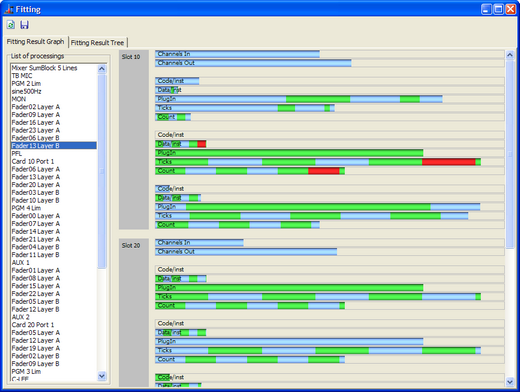
If your Config can not be transferred to a device, although the load display DSP capacity bar is not indicating a 100% load, check the Fitting Report, whether a process might have a 100% load in a storage area. In this case, the process must be modified or the functions have to be reduced.
The Fitting Result Tree tab describes the resource assignment with numeric values.
Click ![]() to update the fitting report.
to update the fitting report.
Click ![]() to save the fitting report, for example in the case of support.
to save the fitting report, for example in the case of support.
Note
The structure of the DSP load is very complex. Please ask the DHD support team if you need to read out further detailed information from the fitting report.
Available Audio/Logic IDs
The content of the Audio and Logic IDs View window is useful if you want third party devices to communicate with the DHD system by an external protocol. Because the audio and logic IDs are assigned dynamically in Toolbox5, it is necessary to take a look at this list.
Project as XML Tree
This function shows the configured data of the Toolbox5 project as XML code. It is especially of interest to developers of third party software applications and hardware that should deal with the configured data of the Toolbox5 project.
Transfer Menu
Connecting the Configuration PC and the Device
To load a Config from a device to the Toolbox5 software or write it back to the device after modifying it, the configuration data has to be exchanged between the configuration PC and the devices. This is done by an Ethernet connection using TCP/IP.
The commands Load to Device and Load from Device load and store a Config to and from the device respectively. In the Toolbox5 software, you can choose between different options, how the configuration PC can exchange data with the device.
In any case, you have to select the desired device from the project tree first and then select the command for up- or download. After that, the DHD Connection Dialog window opens that is identical for both commands:

The devices use the UDP protocol to announce their availability in the network. This requires that UDP packets can be transferred between the DSP frames and the configuration PC. This is not always possible in all networks.
Note
If no UDP packets are transferred between the Toolbox5 software and the devices, the list of all available DHD systems is not shown in the DHD Connection Dialog. In this case, you have to know exactly, which IP addresses belong to which device, and enter them manually in the Fixed IP box.
If the configuration PC and the devices can communicate via the UDP protocol, the list in the DHD Connection Dialog window shows all available systems. You can now select the desired destination from the list.
After transferring a Config to a device, in the status bar of the Toolbox5 window the message Project modified is shown. During the transfer, a time stamp is set in the file that is also transferred to the device. According to this time stamp, the Toolbox5 software can recognize, whether the Config in the device differs from the one in the file. The data stamp of the file or the time of the last transfer are shown under <Device>/Options in the Last changed box. If the Config has never been transferred to a device, no timestamp is shown.
In the project tree, apart from the device name, the term Online is shown if the project ID and the device ID of the project file are identical with the data in the device. If the software Config has been changed compared with the one in the device, the additional message Modified is shown.
There are the following options for setting up a connection:
Select: In the list, all devices connected to the IP network segment are listed. This list is created automatically via UDP broadcast messages that are received from the devices. For each device, the appropriate project ID, device ID and the hardware and device name are shown, as well as the IP address. TheSerial Nocolumn shows the serial number of the device which is identical with the company-specific bytes of the Ethernet MAC address of the device. Select the desired device by mouse clicking.Fixed IP: Here, you can enter the IP address of the device directly. This may be necessary if no UDP packets can be received, if the configuration PC and the device are located in different network segments. For remote servicing of systems this option might be helpful as well.
If you want to connect the device directly to the configuration PC with an ethernet cable, a twisted ethernet patch cable (X-cable, cross cable) has to be used. Assign static IP addresses on both sides (no DHCP). The first 3 bytes of the address must be identical, the last byte must differ, like the following example:
| IP address on Toolbox5-PC | 192.168.010.057 |
| IP address of device | 192.168.010.058 |
| Subnet mask | 255.255.255.0 |
Note on the Configuration of IP addresses
Each device needs an unambiguous IP address that is either set statically or assigned by a DHCP server. The appropriate setting can be found under Network Configuration in the Maintenance Window. (See also Maintenance Window - Servicing Modules)
If the devices are not constantly connected to an IP network, you should use static IP addresses. Do not assign any of the IP addresses twice. Don't operate devices with DHCP enabled if no DHCP server is available on the network.
Load to Device
This command copies the current Config from the Toolbox5 software to the selected device. To do this, first select the device in the project tree, the Config of which you want to copy and then use the command Load to Device. The DHD Connection Dialog window opens, in which you can select the desired device. (See figure DHD Connection Dialog window for connections with the device above) After confirming the selection, the new Config is transferred. If the name of the device in the project and the one of the device selected in the network should not be identical, the following message is shown:

Warning
Loading a new Config overwrites a Config already existing in the device. Therefore, if in doubt, save the current Config before making any changes using the Load from Device command and save it to a file.
The command Load to Device can also be executed by clicking in the toolbar.
Load from Device
This command loads a Config from a device to the Toolbox5 software. If you use a project file with several devices, make sure to select the correct device before selecting the command. In the DHD Connection Dialog window you must select the corresponding device. (See figureDHD Connection Dialog window for connections with the device above)
Note
If the device you are downloading a Config from is already included in the project, it is automatically selected in the DHD Connection Dialog. This requires identical values for project ID and device ID both in the project and the device itself.
Alternatively, you can create an empty project and insert an empty device by clicking Add or using the contextual menu. Then, load the Config into this empty device.
Further on, you can select a device in a loaded project file and overwrite its Config with data from a device using the command Load from Device.
Warning
Be aware that changes of the project caused by downloads can not be undone, as soon as the project file is saved. Therefore, for safety reasons, always work with copies of the original project files.
Loading a Config from a device is not useful to rebuild a complete project, because the global project settings (global logics and global potentiometers, settings of the talkback system, authorization groups and user accounts, linked devices and so on) are not loaded from the device. That is why you should always work with the last status of the project file because the central resources named above have to be identical for all devices in the project. If you load the data for global functions from other devices, these might overwrite the settings of the current project file!
In general, it is always better to save the current Config of a project as project file. If then other changes become necessary, load the project file again and modify it. After that, load the new Config to the corresponding devices. This way, the project file is always up to date and is available as a backup for the configuration data in the devices at the same time.
You can execute the command Load from Device also by clicking ![]() in the toolbar.
in the toolbar.
Options Menu
With the settings in the Options menu, only options are set that affect the operation of the Toolbox5 software. They have no effect on the configuration of the devices.
Configuration
After selecting Configuration, the Toolbox Configuration window opens. The options are explained in detail in the following table.
You can select this option also by clicking ![]() in the toolbar.
in the toolbar.
Files-Tab
| area | option | description |
|---|---|---|
| Project Files Save | Backup Levels | • Define here, how many backup generations shall be created. (min.=0, max.=100) |
| Auto Save each | • If this check box is selected, the software creates backups of the project file automatically. • The number of backup files can be set in the Backup Levels box. If the last file is written, the first is overwritten when saving the next time. This way, it is lost!• The desired interval between two backups can be entered in the Auto Save each (min.=0 minutes, max.=100 minutes) box.• The created backup files have the number of the backup in their extensions, for example .dd1. The higher this number is, the newer is this file. If you want to use such a file in the Toolbox5 software again, previously you have to change its extension to .ddp again. |
|
| File Menu | Show recently used files list | • If this check box is selected, only the defined number of recently opened projects is offered as a quick start option in the File menu. • The desired number of entries can be defined in the Show recently used files list box. (min.=0 entries, max.=100 entries) |
View-Tab
| area | option | description |
|---|---|---|
| Navigator | View follows selected object automatically | • By selecting this check box, the content of the navigator automatically adapts to the options and functions that are currently edited. |
Audio and Logic Sources-Tab
| area | option | description |
|---|---|---|
| Audio and Logic Tree | Hide sources without label | • This option influences the Audio sources window. (See also Audio Sources) If it is enabled, audio sources with deleted labels in the DSP Frame I/O, are deactivated. (See also DSP Frame I/O – Configuring the DSP Frame) |
| Assignment | Automatically select next item | • Select this check box to work quicker when defining the output routing: In this case, the Toolbox5 software selects the following output automatically when assigning audio signals to the outputs - in the output list as well as in the list of audio signals in the Audio Sources window. (See also Output Routing) |
Enter feature key
This function is only useable by DHD.
Help Menu
About
If you select About, the Information window opens.
Here, the date of creation of the software and the version of the used Toolbox5 are shown, for example Version 6.4.4.0 Please always mention the complete version name when asking for servicing.
The version number of the DHDCS that is included in Toolbox5 is also shown in this window.