I/O Overview
In the I/O Overview section, you can add, remove and configure all inputs and outputs (Audio and Logic), that belong to your system. You can configure I/O boxes, sub-modules and device interlinks.

To add an I/O unit to the system, click Add, a list with different I/O units is shown. Select your I/O unit from the list, now it is available in the Select element area.
Here, you can also select device interlinks and Ember+ I/O connections.
To delete a selected I/O unit from the list, click Remove.
If you do not see your product, click Click here to see more modules or the menu Options/Configuration…/Product filter. Here you can set the product filters.
If an I/O unit is selected in the Select element area, all corresponding audio inputs and outputs are shown in the Inputs/Outputs area.
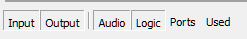
Above this list you can see a set of buttons, which allows you to filter the list for Input, Output, Audio, Logic (GPIO ports), Ports (to show all ports on an I/O module) and Used(only shows all used ports).
To show your required elements, click on the the corresponding button. To hide elements you need to deactivate the corresponding button.
Options
List Columns
Colums in the Inputs/Outputs area:
| Column | Description |
|---|---|
| Tag | Allows tagging inputs and outputs. See more at Object Tags |
| Original Label | This column shows the internal label which is generated in that scheme: <module type>.<port label> |
| Label | Individual Label, double-click on the label and change the current name. |
| Stereo | Indicates if the signal is mono or stereo. |
| Info | Indicates type of Logic Triggering for GPO ports (ON/OFF/Pulse on activate/Pulse on deactivate) |
| Source | Shows the assigned audio/logic source for output ports. |
| Mute | Shows that a Mute Logic is assigned to an output. (*-Symbol) |
Unit Options
If you select a module in the select element section, the Unit Option area on the right hand side will show general information and options.
| option | description |
|---|---|
| Type / Description | Additional information on module type. |
| Module Name | Enter a distinctive name for the selected input. |
| Mounting Location | Select the mounting Location of the module as in Mounting Locations. |
| Operation Mode | Select operation mode of the module. Depending on module type you can select e.g. number of channels (MADI Modules) or headroom options (Multi I/O). |
| Level Adjustments (D/A) | Depending on module type, you may adjust levels of all digital or analog Inputs/Outputs of the module here. |
| Device Password | If a 52-7067 AES67 interface is selected, you can set a password for its web interface here. See more at Device Password. |
| Licenses | When using a 50-7067 AES67 interface, you can enable licenses here. Learn more about licenses available for AES67 here. |
<module>.<port> Audio Inputs
| option | description |
|---|---|
| Type of Signal | Shows the general signal type of the port. |
| Enter Label | Enter a distinctive name for the selected input. |
| Select M/S | Select, if the signal is mono or stereo. |
| Default Source Stream | If you use a 52-7067 AES67 interface, you can select a default source stream to receive. If you run a Toolbox project with multiple AES67 RAVENNA Interfaces, you can click …. The AES67 source tree opens. Select the stream you want to subscribe to and click Assign. If you have an AES67 device outside the current Toolbox project, you can enter a stream name by hand here. The AES67 RAVENNA Interface will use this as default source. This field is required when Locked via Toolbox is checked. |
| Level Adjust | Adjust leveling / headroom for each input from the corresponding drop-down menu. The shown values always refer to the devices internal default level of 0 dBint. |
| Sample Rate Converter | Select from the drop down menu, if the sample rate converter is activated (On) or deactivated (Off) for this input. |
| Locked via Toolbox | Only for AES67 interfaces. When locked, all stream parameters are set to DHD defaults and can not be changed. The AES67 RAVENNA Interface will enable the stream directly after sending the config to the device. The AES67 RAVENNA Interface will try receiving the Default Source Stream defined in Toolbox after sending the config to device. |
Adding to Mixer
Select Add to Mixer 1 check box to create a fader channel in Mixer 1 with that signal as audio source. Following options will be shown:
| option | description |
|---|---|
| Fader Start Level | Select a level, which sets the fader start logic to on. |
| On Start | The faderstart is only activated and deactivated by pushing the On/Off key, not by moving the fader. |
| Auto Off | By closing the fader, the channel is automatically switched OFF (ON key is deactivated). |
| Clean Feed | Select this check box to create a corresponding clean feed bus for this signal. |
| Timer Reset | If this check box is selected, opening this fader will reset and start the Auto timer of the stopwatch. |
| Channel On Logic | Select a Logic Function from the Logic Sources window, which sets the channel to ON. You can choose, for example a GPI to open a channel. |
| Channel Off Logic | Select a Logic Function from the Logic Sources window, which sets the channel to OFF. You can choose for example a GPI to close a channel. |
| Mute Condition Logic | Click Source to select a Logic source that mutes the input if the logic source becomes true. |
| Analog Gain | Default value for analog gain. Note Some analogue I/O cards do not provide all gain values |
| P48V | Turn Phantom Power On/Off by default |
<module>.<port> Audio Outputs
| option | description |
|---|---|
| Type of Signal | Shows the general signal type of the port. |
| Enter Label | Enter a distinctive name for the selected output. |
| Level Adjust | Adjust leveling / headroom for each input from the corresponding drop-down menu. The shown values always refer to the devices internal default level of 0 dBint. |
| Select M/S | Choose if the signal is mono or stereo. |
| Sample Rate Converter | Select from the drop down menu, if the sample rate converter is activated (On) or deactivated (Off) for this output. |
| Dithering | If you connect devices with a lower resolution of the digital signals to a DHD device, here you can define how the internal audio signal is to be dithered before leaving the digital output. With this function, the quality of the output signal can be improved. You can select 16 bit, 20 bit, or Off (no dithering, preset value). |
| Digital Out Mode | This option can adopt the values Pro (default value) or Consumer. See the parameter details below - Digital Outputs - Pro and Consumer valuesInfo Especially for consumer and semiprofessional DAT or MiniDisc devices, you should use the Consumer option because they might not synchronise properly in which case they display No Lock, for example. |
| Source | You can assign an audio signal to a mono output. Click the Source button, the Audio sources window opens. Select an audio source, and click Assign. |
| Left Source | You can assign an audio signal to the left channel of the selected output. Click the Source button, the Audio sources window opens. Select an audio source, and click Assign. |
| Right Source | You can assign an audio signal to the right channel of the selected output. Click the Source button, the Audio sources window opens. Select an audio source, and click Assign. |
| Direct ACI | Select this check box to enable volume control for the headphones via a potentiometer which is connected to an ACI. This option is only available for headphone outputs. The ACI on D-sub port 1 is assigned to headphone 1 (HP1) and the ACI on D-sub port 2 is assigned to headphone 2 (HP2). |
| Mute Logic 1 | Select this check box to mute this output, if a fader with one of the inputs with selected Mute Logic 1 check box is opened. |
| Mute Logic 2 | Select this check box to mute this output, if a fader with one of the inputs with selected Mute Logic 2 check box is opened. |
| Mute Logic 3 | Select this check box to mute this output, if a fader with one of the inputs with selected Mute Logic 3 check box is opened. |
| Mute Logic 4 | Select this check box to mute this output, if a fader with one of the inputs with selected Mute Logic 4 check box is opened. |
| Mute Logic 5 | Select this check box to mute this output, if a fader with one of the inputs with selected Mute Logic 5 check box is opened. |
Digital Outputs - Pro and Consumer values
On digital outputs you can choose between Pro (default value) or Consumer. The following parameters are changed accordingly:
| Mode | Pro (Default) | Consumer |
|---|---|---|
| Terminator | 110 Ohm | 75 Ohm |
| Output voltage | 5 V | 0,5 V |
| Data stream | Professional Bit set | Consumer Bit set |
IOModule-X.<port> General Purpose Inputs (GPI)
| option | description |
|---|---|
| Type of Signal | Shows the general signal type of the port. |
| Enter Label | Enter a distinctive name for the selected input. |
IOModule-X.<port> General Purpose Inputs (GPO)
| option | description |
|---|---|
| Type of Signal | Shows the general signal type of the port. |
| Enter Label | Enter a distinctive name for the selected input. |
| Select Source | You can assign a logic sources to the selected GPO. Click the Source button, the Logic sources window opens. Select a logic source, and click Assign. |
Device Interlink
To exchange audio signals directly between two 52/XC, 52/XC2, 52/XD, 52/XD2, 52/XS, 52/XS2 cores, you can connect them directly by a shielded CAT5 or CAT6 cable on an APC port on each DSP core.
Important
To use the DeviceLink, each DSP Core requires a 52-8582 XC/XD/XS Core Audio Network license. See licensing page for general information on licensing.
Each APC Interlink connection can send and receive 48 audio channels at the same time. This connection does not transmit any control signals.
Each GA Interlink supports from 32 up to 512 channels. (Set number of needed channels in Operation Mode)