Table of Contents
Administration Menu
Note
The functions of the Administration menu are only executable by administrators.
Channel Groups
Channel Groups contain single channels, which are related to each other.
Stereo signals can be seen as simple channel groups. However, it is not necessary to configure stereo groups, because this is done automatically.
If a channel group should contain more than one stereo signal, the group needs to be created separately, e.g. for all 6 channels of a 5.1 signal.
It is possible to create channel groups for inputs and for outputs.
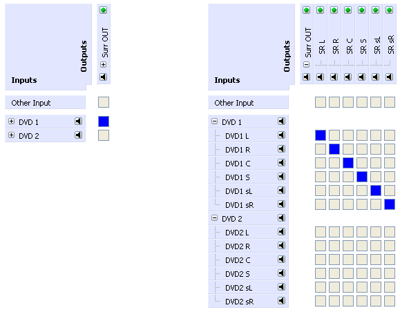
With the aid of channel groups, it is possible to control a number of signals by switching only one single crosspoint. So, you can reduce the effort concerning the number of needed crosspoint switchings and you will also get a better overview in the matrices.
The connection of channel groups always results in a 1:1 routing. That means, that the first channel of an input group is always connected to the first channel of the output group, the second input to the second output and so on.
If there is a different number of channels in the connected input group and output group, the 1:1 routing is used until any channels of the input group or the output group are connected.
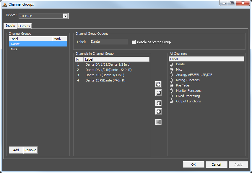
After selecting the entry Channel Groups in the Administration menu the Channel Groups window appears. Alternatively, you can reach this window by clicking the  symbol in the toolbar.
Select the desired device in the pull-down menu on top of the window if the project includes several devices.
Use the buttons Add and Remove to create and delete input and output groups. Give your channel groups significant names in the text box Label. In the channel groups, you can use all available channels of the list All Channels. Drag'n'drop the signals from the right-handed list All Channels to the list Channels in Channel Group or use the arrow buttons (left & right) between the lists. You can change the order of the channels within the list Channels in Channel Group per drag'n'drop or with the arrow buttons (up & down).
Press Apply to save your settings if you want to continue with the channel group configuration or press OK to save and close the Channel Groups window. It is possible to undo all settings and reload the state you had saved last by pressing Cancel.
From now on, you can insert the created groups into your matrices.
Channel Properties
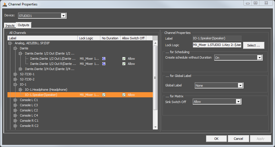
After selecting the entry Channel Properties in the Administration menu the Edit Channels window appears. Alternatively, you can reach this window by clicking the  symbol in the toolbar.
Within this window, you can set some options for the input and output channels.
Select the desired device in the pull-down menu on top of the window if the project includes several devices.
The Inputs tab shows all inputs of the chosen device. Mark an input of the All Channels list to be able to change its name in the Label text box.
The same applies to the output channels on the Outputs tab, but there are more options for output channels.
With the Lock Logic it is possible to fix the routing for the respective output. That means, as long as the selected logic is true, the routing of the output can not be changed. Therefore, double click on the desired output in the Lock Logic column or click the Select button in the Lock Logic line of the Channel Properties area and select a logic source. In the Logic Sources window you can choose the Invert Logic Level option if you want to use the logical state inverted. If the logic is used inverted, this is shown by an exclamation mark in front of the logic source name in the Lock Logic column.
In the … for Scheduling area you can set the global default for new schedules on the output you selected in the Create schedule without Duration option. Possible options are:
(Use global Default): Use the global default as defined in Scheduler Options.On: Always create a schedule without a predefined duration on this output.Off: Always create a schedule with a predefined duration on this output.
In the … for Global Label area, you can define which global label shall be overwritten to contain the name of the source routed to this output. Select the desired global label in the dropdown list on the Global Label option.
Moreover, you can define what should happen, if a user wants to switch off a crosspoint. Therefore, double click the desired output in the … for Matrix area or choose the desired option from the Sink Switch Off pull-down menu in the Channel Properties area. Three options are offered:
Allow: It is possible to switch off a crosspoint.To Default: A predefined source is connected to the output automatically. Afterward, it is possible to select another source, but not to switch off the crosspoint of the predefined source.Deny: It is possible to select another source, but not to switch off a crosspoint. Hence, it is guaranteed that always an input is connected to the output.
The Allow option is set by default for all channels.
If the To Default option is selected, you also have to choose an Off Source. Click the Select button in the Off Source line and choose the input signal that should be routed to the output when switching off the current connection.
All modified channels are marked in the Mod. column, until you save the current settings.
Press Apply to save your settings if you want to continue editing channels or press OK to save and close the Edit Channels window. It is possible to undo all settings and reload the state you had saved last by pressing Cancel.
Channel Categories
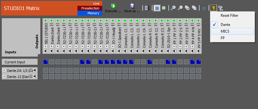
To make the matrix and the list view more clear, you can hide groups of inputs and outputs. Beforehand, you need to merge the desired signals in channel categories.
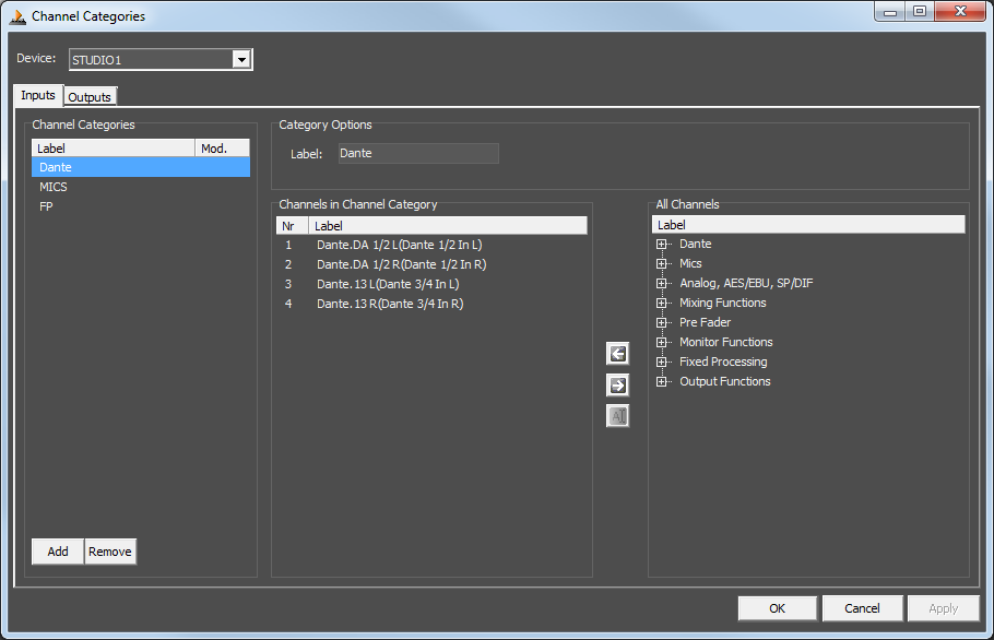
To create channel categories, select the entry Channel Categories in the Administration menu. The Channel Categories window appears. Alternatively, you can reach this window by clicking the  symbol in the toolbar.
Select the desired device in the pull-down menu on top of the window if the project includes several devices.
Use the buttons Add and Remove to create and delete input and output categories. In these channel categories, you can use all available channels of the list All Channels. Drag'n'drop the signals from the right-handed list All Channels to the list Channels in Channel Category or use the arrow buttons between the lists.
Press Apply to save your settings if you want to continue editing channel categories or press OK to save and close the Channel Categories window. It is possible to undo all settings and reload the state you had saved last by pressing Cancel.
To adjust which inputs are shown in the matrix or list view, click the  symbol. A contextual menu appears and you can select the desired channel categories. The same applies to the outputs in conjunction with the
  symbol. If no channel category is selected, all channels are displayed.
Matrices
The Matrices window appears, wherein matrices can be created and edited. Alternatively, you can reach this window by clicking the  symbol in the toolbar.
Find detailed information on creating matrices in the section Configure Routing Matrices.
User Accounts
The User Accounts window appears, wherein users can be created and edited. Alternatively, you can reach this window by clicking the  symbol in the toolbar.
Please find detailed information on user administration in the section User Management.
Workstations
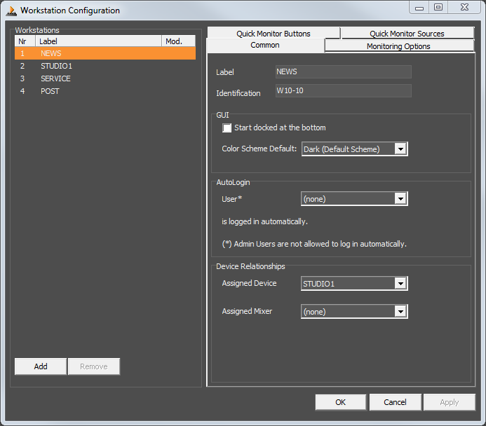
The Workstation Configuration window appears. Alternatively, you can reach this window by clicking the  symbol in the toolbar.
The configured workstations for the operation of the DHDOM are listed in the Workstation Configuration window. Use the buttons Add and Remove below the list to add and delete workstations. Every workstation that was connected once is listed even if it was not configured manually.
Common
The Identification must be identical with the windows PC name of the respective workstation. In the text box Label you can enter any name. The labels are used to identify the workstations within the DHDOM during the configuration process. If a workstation was not added manually but was used to login to the DHDOM, the Identification and the Label are set to Windows PC automatically.
Activate the checkbox Start docked at the bottom if you want the DHDOM to get started in a reduced view. A default color scheme can be chosen, that should be loaded automatically. How to create and edit color schemes can be found in Options Menu / Colors section.
A user can be chosen in the User menu who is automatically logged in when starting the DHDOM.
With the Device Relationship settings below you can define to which device and - if available - to which mixer a workstation is assigned. This assignment is important for the following functions:
- Login on Console: If the user logs in at the DHDOM and should be logged in at a console simultaneous, this console need be defined here. (
User Accounts / Console Options > Allow Console Login) - Load Mixer Snapshot on Login: For every user, a mixer snapshot can be selected that is loaded automatically at the here defined console when the user logs in. (
User Accounts / Snapshot Configuration > Mixer Snapshot on Login) - Monitoring: The relationship to a device is also necessary for the monitoring output that should be assigned to a workstation because only the outputs of the selected device are available for monitoring purposes. (Workstations
/ Monitoring Options > Use Monitoring + Used Output)
Press Apply to save your settings if you want to continue with the workstation configuration or press OK to save and close the Workstation Configuration window. It is possible to undo all settings and reload the state you had saved last by pressing Cancel.
Monitoring Options
Detailed information on the settings of this tab can be found in the section Monitoring.
Quick Monitor Buttons
A precise description of Quick Monitor Buttons can be found in the section Quick Monitor Buttons.
Quick Monitor Sources
Find out more about the settings of the Quick Monitor Sources tab in the section Monitoring Sources.
Press Apply to save your settings if you want to continue with the workstation configuration or press OK to save and close the Workstation Configuration window. It is possible to undo all settings and reload the state you had saved last by pressing Cancel.
Special Days
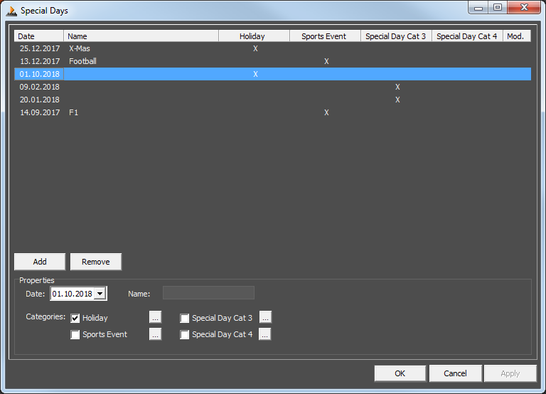
The Special Days window appears. Alternatively, you can reach this window by clicking the  symbol in the toolbar.
In the Special Days window you can configure an arbitrary number of special days and assign them to up to four groups. These groups can be used for scheduling. (See Scheduling)
The basic idea of the Special Days is to interrupt repeat patterns on desired days. That means, if a Special Day is created and is assigned to a Special Day Category, all scheduled events are not executed on this Special Day unless the respective Special Day Category is selected for this event.
Use the buttons Add and Remove to create and delete special days. Select the desired date and name the special day. Each day needs to be allotted at least to one of the four groups (Categories). Click the  symbol behind a group if you want to change its name.
Press Apply to save your settings if you want to continue with setting up special days or press OK to save and close the Special Days window. It is possible to undo all settings and reload the state you had saved last by pressing Cancel.
Remote Control Views
If you select this entry of the menu, the View Editor appears, wherein remote control views can be created and edited. Alternatively, you can reach this window by clicking the  symbol in the toolbar.
Please find detailed information on the view editor in the section Creating Remote Control Views.
Snapshot Options
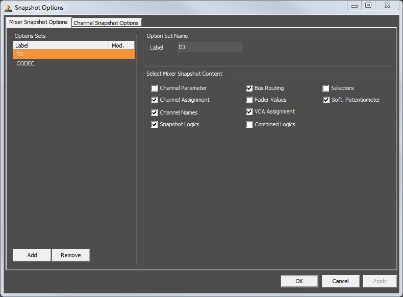
In the Snapshot Options window, you can edit option sets for mixer and channel snapshots.
The Option Sets are used in DSP control for transferring snapshots.
Mixer Snapshot Options Tab
Add an option set. You can add option sets in the left column by clicking Add and delete them by clicking Remove. Then give the options set a name using the Label field on the right side. Then you can select, what options the mixer snapshot should contain in the Select Mixer Snapshot Content area.
- Channel Parameter
- Channel Assignment
- Channel Names
- Snapshot Logics
- Bus Routing
- Fader Values
- VCA Assignment
- Combined Logics
- Selectors
- Soft. Potentiometer
Channel Snapshot Options Tab
Add an option set. You can add option sets in the left column by clicking Add and delete them by clicking Remove. Then give the options set a name using the Label field on the right side. Then you can select, what options the mixer snapshot should contain in the Select Channel Snapshot Content area.
- Channel Parameter
- Bus Routing
SNMP Options
Open the SNMP Options window to set up SNMP. See SNMP Documentaion for more details.
External Devices
External Devices are used in addition to event_scripting and are only configured by DHD audio.
Event Scripting
Event Scripting is the possibility to extend OS & OM functionality by DHD scripts. This function is only configured by DHD on demand.
Remote Routing
Remote routing is a routing operation on a remote DHD device triggered by another DHD device. This data is transferred via OS. See the image below.
Example: Tie line routing
If you do not have enough lines available on e.g. a production console, you can use remote routing. With that function, the console can request a routing of a tie line on the matrix core. This is an easy way to same tie lines between cores.
The production console can request a tie line (remote) routing at OS. The OS forwards this request as a routing command to the matrix core. The matrix core then routes the audio (as in the image above).
Configuring Remote Routings
To configure remote routings, two sides must be configured.
Toolbox Side
- On the Device that requests routings, add a
Button List 2015element with the functionRemote Routingand give it the correct list address so OS can identify the request. See Toolbox8 / Button List 2015 TFT Element.
OM Side
First, configure the remote source list. This list defines the sources that are available for the device for routing.
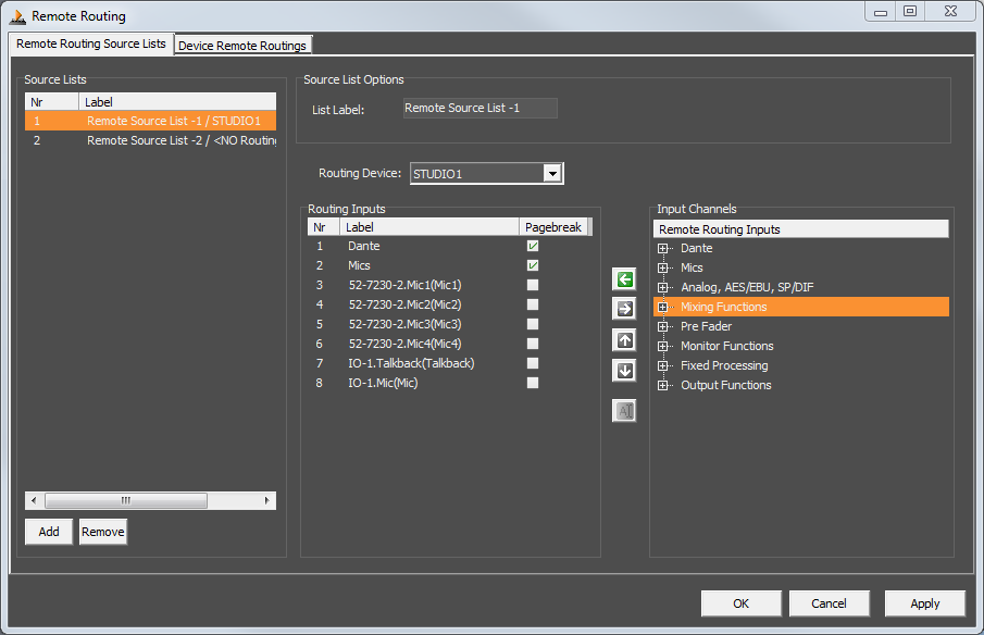
To configure a remote routing source list, first, click Add in the Source Lists area on the left. Click on the newly created list. Then, on the right-hand side, you can edit the label in the List Label field.
Select the device, where the remote routing shall be performed in the Routing Device drop-down list. After this selection, the available input channels of the device will be displayed in the Input Channels area. To enable/disable input channels for remote routing, add them to or remove them from the Routing Input list by clicking the arrows.
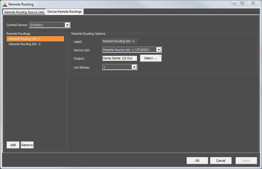
After you added a remote source list, go to Device Remote Routings tab. First, select the device that will be controlled in the Control Device drop-down list. Add a new remote routing in the Remote Routings area on the left.
Edit the name of the remote routing using the Label field.
Select the matching source list you created which the routing shall take as the base for using the Source List dropdown. Then Select the Output, where the routing shall be performed. Then select a free list address. The list address must match with the list address given in Toolbox (see toolbox_side above).
Click Apply to apply the changes.
