Routing in the Matrix View
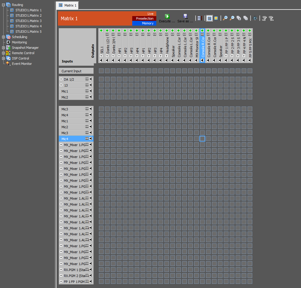
The Operation Manager view is divided into two parts. In the left-handed list, you can select a matrix (for routing and/or scheduling, depending on the settings) or other options. In the right part of the window, the options of the selected process are shown. Double-click the name of a matrix in the left part of the window to enable the matrix view in the right part. Click the  symbol in the configuration part to activate the matrix view. Alternatively, you can reach the matrix view via the menu entry
 Matrix/Matrix View. It is possible to open several matrices at once in different tabs to quickly switch between them.
Switching the crosspoints can be done in 3 different ways:
LiveMode: You can connect and disconnect crosspoints directly by clicking them.PreselectionMode: Click on an arbitrary number of crosspoints to preselect there states. Afterwards, all states of the crosspoints can be sent at the same time to the device by pressing theExecute…button.MemoryMode: In this mode, crosspoints can be set without influencing the current configuration. Save these settings in memories to load and execute them in theLiveandPreselectionmode.
If an output is already used by an input of another matrix, this is indicated by the crosspoints of the row Other Input (only in Live and Preselection mode). The respective outputs can be connected to the inputs of the current matrix, provided that they are not locked. Click the green dot  at the output to lock a channel. Thereupon a red cross is shown instead of the green dot. The routing of this output is now locked and can not be changed directly, but the scheduler passes this lock. You have to click the red cross to enable the output. The state of the output is adopted in all matrices, that include the respective output.
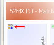
Upcoming scheduled events for an output within the next hour are shown by the  symbol below the green dot or the red cross in the respective column.
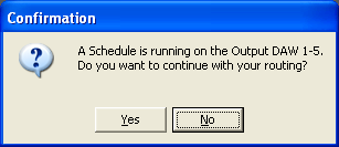
The assignments to outputs that are currently used by the scheduler are not directly set.
In this case, a message appears and you have to confirm, that you want to overwrite the scheduled task.
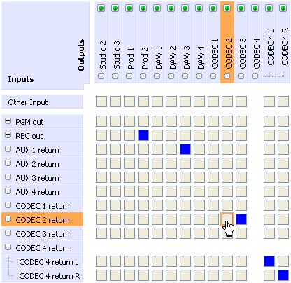
Click the plus sign in front of a signal group to be able to set its subchannels independently. Use the minus sign to minimize the view of the branch.
In the Memory mode you can find the line Don't Change on top of the matrix instead of Other Input. All crosspoints of this line are activated by default after you have created a new memory. Without this function, the complete matrix would be reset, because no crosspoints are activated. If you activate a crosspoint of the memory, the Don't Change selection disappears for the respective output. It is possible to reselect the Don't Change option later on. If you want to deactivate the routing to an output with the memory, you need to assign any input to the output and to deactivate this crosspoint subsequently. This way, the Don't Change option is canceled and no input is routed to the output.
Crosspoint States
| Crosspoint State | Meaning |
 | A crosspoint is outlined orange when the mouse cursor is pointing to it. The marked crosspoint is switched by left clicking it. In this picture, the marked crosspoint is not active. |
 | The crosspoint is active. If this crosspoint represents a connection of collapsed channel groups, blue stands for a 1:1 connection between this groups (e.g. a stereo input signal routed to a stereo output: “left in” to “left out” and “right in” to “right out”). |
 | The crosspoint is set to active in the software, but there is no reply from the device yet. Normally, this option is only shown for a short moment in the period between activating the crosspoint and receiving the acknowledge from the device. If this crosspoint represents a connection of collapsed channel groups, blue stands for a 1:1 connection between this groups (e.g. a stereo input signal routed to a stereo output: “left in” to “left out” and “right in” to “right out”). This state is only displayed in Live mode. |
 | The crosspoint is deactivated in the software, but there is no reply from the device yet. Normally, this option is only shown for a short moment in the period between deactivating the crosspoint and receiving the acknowledge from the device. You will see this state, too if you want to deactivate a crosspoint that is blocked by the Channel Properties settings (see also Channel Properties). If this crosspoint represents a connection of collapsed channel groups, blue stands for a 1:1 connection between this groups (e.g. a stereo input signal routed to a stereo output: “left in” to “left out” and “right in” to “right out”). This state is only displayed in Live mode. |
 | This crosspoint represents a connection of collapsed channel groups with active connections between this groups, but no 1:1 connection (e.g. a stereo input signal routed to a stereo output: “right in” to “left out” and “right in” to “right out”). |
 | The crosspoint is set to active in the software, but there is no reply from the device yet. Normally, this option is only shown for a short moment in the period between activating the crosspoint and receiving the acknowledge from the device. This crosspoint represents a connection of collapsed channel groups with active connections between this groups, but no 1:1 connection (e.g. a stereo input signal routed to a stereo output: “right in” to “left out” and “right in” to “right out”). This state is only displayed in Live mode. |
 | The crosspoint is deactivated in the software, but there is no reply from the device yet. Normally, this option is only shown for a short moment in the period between deactivating the crosspoint and receiving the acknowledge from the device. You will see this state, too if you want to deactivate a crosspoint that is blocked by the Channel Properties settings (see also Channel Properties). This crosspoint represents a connection of collapsed channel groups with active connections between this groups, but no 1:1 connection (e.g. a stereo input signal routed to a stereo output: “right in” to “left out” and “right in” to “right out”). This state is only displayed in Live mode. |


