Setting up configurations
Adding a device
Click Add, below the project tree. A menu of possible device types opens. The following device types are available:
52/XCadds a 52/XC mixing device, which can be used with all Series 52 control modules (52/MX, 52/RX, 52/SX, 52/DX)52/RM4200Dadds a mixing device based on RM4200D DSP frame with an Series 52 communication controller (RM420-852B, RM420-853B). A new device appears in the project tree. On the Options tab, select 52/MX or RM4200D in the Console type list. It depends on which console type you are using with your device. (see also Device Properties / Options)52/XR Routeradds a 52/XR Routing Device to the project.52/SX Configadds a 52/SX mixing device, which can be configured by the SXConfig configuration assistant.
Download
For information about the configuration of a 52/SX device, see 52/SX Mixing Console Manual which is available on our Website as Online Manual or PDF version.52/DX Configadds a 52/DX mixing device, which can be configured by the DXConfig configuration assistant.Third Party Deviceadds further devices to the project, which the DHD mixing and routing systems are able to communicate with. These devices can not be configured using Toolbox5.
Click Remove to delete a selected device from the Project.
Alternatively, you can add devices using the context menu by right-clicking on the project tree or the area around.
The project tree
You can find the project tree in the Project area of the main window in Toolbox5. The project tree includes the Global Control section and all devices in your project which are shown with their appropriate names. In front of the Global Control sections and the devices you can see a plus symbol. This symbol indicates a node with subsections. Click on a plus symbol to get access to different parts of the configuration. (See also figure Toolbox5 Project Options, General Options.) To navigate through the project tree use the left mouse button, some functions can also be accessed using contextual menus by pressing the right mouse button.
To add a new device to the project click Add or use the contextual menu.
If a device is selected, you can remove it by clicking Remove Device or using the contextual menu.
Sections in the project tree, which can be renamed by the user, for example a mixer, are written in this manual in angle brackets < and >. A typical path in the project tree is, for example <device>/<mixer>/Fader Channels.
Project characteristics
Select the top entry in the project tree. The Project Options tab is shown on the right-hand side of the Toolbox5 window.
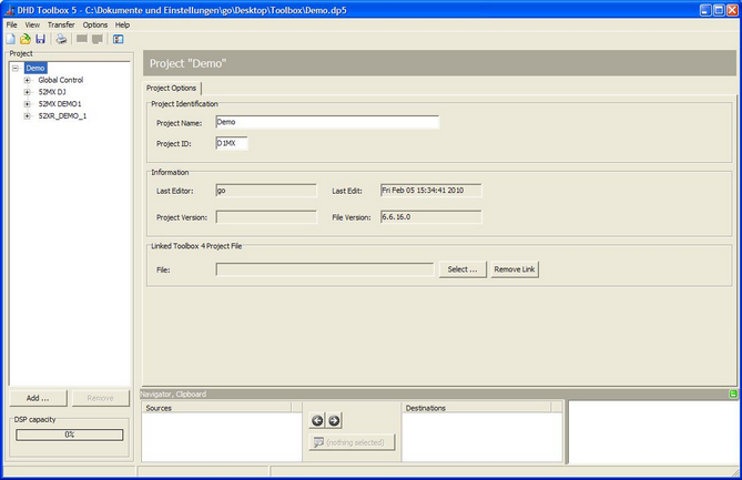
Project Options
A project can be clearly identified by the Project Name and Project ID text boxes. The project name is shown as the top entry in the project tree, it has no further functions. The project ID is transferred to the devices because it is necessary for the communication via the UDP protocol. If several devices are exchanging Global Functions via the network, they must have the same project ID.
Important
If different Toolbox5 projects are operated in the same network segments, their project IDs have to be different!
A project ID consists of 4 ASCII digits which is a 32 bit address for clear identification. If you set up a new project, the project ID is generated randomly. It is always possible to change the project ID.
The project ID is shown also in the Maintenance Window in front of the corresponding device name as well as in the window for loading a configuration to or from a device (DHD Connection Dialog).
In the Information area on the Project Options tab you can see, who edited the project last (Last Editor), and when the project was edited last (Last Edit). For the name of the person who changed the project, Toolbox5 enters the current Windows Login name. The Project Version box is for information only, a further functionality has not yet been implemented.
It is possible to link a Toolbox4 project to a Toolbox5 project. Click Select in the Linked Toolbox 4 Project File area and choose the respective Toolbox4 project file. All data that is relevant for the Toolbox4 project is automatically exported to the linked project (e.g., global logics).
Global control
The Global Control area contains the tabs Logic, Resources, Potentiometer and Channel Snapshot Types. The settings of these tabs are explained in the following subsections.
Logic - Global Logics
Note
Global logics are only included in Toolbox5 to keep it compatible with RM4200D systems. This function is no longer used with systems of the Series 52.
If several devices are connected by Ethernet, they can exchange global logics using UDP commands.
These devices are managed within one project. This makes configuration easier and secures a correct assignment of the appropriate devices. This way, all receive the same project ID.
Important
In order to enable all devices to exchange global logics via UDP, their project IDs have to be identical.
In a project, you can use a total of 200 global logics. Each of these functions can be fed with any logic source of the devices in the project. All global logics are available as logic sources in each device of the project.
Note
If the devices are connected by the serial RS232 interface, only the global logics 1 to 50 can be exchanged. This communication is compatible with RM3200D.
To assign a global logic, follow these steps:
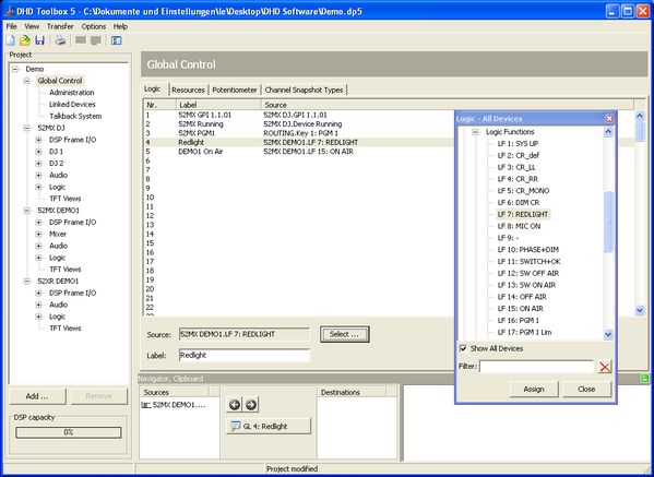
- In the project tree, select Global Control.
- Select the Logic tab. You see a list of all 200 available global logics.
- Click on a row in the Logic table to select the desired global logic.
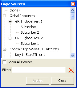
- Click Select, the Logic Sources window opens. Alternatively, you can double-click on a global logic.
- Select the desired logic source by clicking on its entry. Now click Assign or double-click on the logic source. As a result, it is shown in the row of the selected global logic in the column Source.
- You can assign a distinctive name to the global logic in the Label text box.
Tip
If the Logic Sources window is open, you can assign the logic sources also by drag & drop.
Resources - Global Resources
Overview
Global resources are in a way similar to global logics. They are intended to assign single audio sources in a studio complex with several DHD systems exclusively to certain users. A typical scenario may be a central phone line, the return line of which can be fed selectively by two or more studios. But only one studio can own the line at a time. The following figure illustrates such a situation. Here, the CONTROL device is the master, in which the global resources are coordinated. All other devices are subscribers that access the resources alternating.
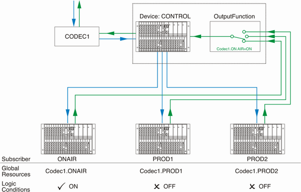
Global resources offer the functions which are necessary to enable the exclusive ownership of a resource and the change of the owner on request. The functions are based on the following design principles:
- A global resource is offered or published by exactly one master. One or more subscribers are defined and can own this resource. You can define up to 20 global resources.
- A resource can either be idle (no subscriber) or owned by exactly one subscriber. You can define which condition a global resource can have after switching on or resetting a device. It can either be idle or assigned to a certain subscriber.
- Master and subscriber are different devices in the same project. But it is possible to define master and subscriber on the same device.
- The master is only defined to determine the device responsible for managing the global resource. It has no additional function.
- Global resources are implemented as special logic signals. For each subscriber of a logic source, there is exactly one global logic signal that can be accessed by all devices in the project. This logic signal is active if the corresponding subscriber owns the resource. At the same time, the logic signals of all other subscribers are inactive.
- Toggling between the different subscribers is done using special key functions. These have to be assigned to keys on the console, which will be explained in detail later on.
- Global resources only enable the toggling of logic signals. The audio signals themselves are controlled using output functions or super output functions, while the logic signals of the global resources are controlling these output functions.
You can define up to 20 global resources that all can be used by the same project. Therefore, the devices must be connected by Ethernet and able to exchange UDP messages.
Important
Make sure all devices have the same project ID! Otherwise, you are not able to exchange UDP messages and the global resources do not work.
Defining Global Resources
To define global resources, in the project tree select Global Control and click on the Resources tab.
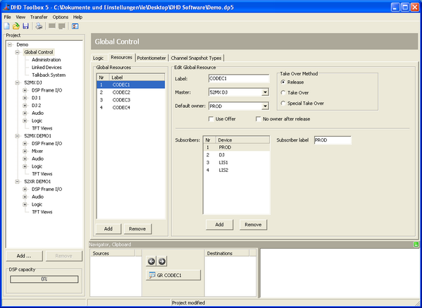
Now follow these steps to define a global resource:
- In the
Global Resourcesarea, clickAdd, to set up a new resource. In theLabelbox, type a distinctive name. - In the
Masterlist, select the device that is to manage the global resource. It is not necessary to define a subscriber on the device as well - but you can if it makes sense.
Note
You can define any device as master. But we recommend to choose the device that the resource (e.g., the phone line) is really connected to. This way, you make sure the line is also available if the master device is active. - Now determine which devices have subscriber access to the global resource. Under the
Subscriberslist, clickAddto create a new subscriber. In theSubscriber labelbox, enter a distinctive name. - Set a default owner in the
Default Ownerlist. This is the subscriber that owns the global resource by default after switching on or reset the master device. The default subscriber is also assigned if a subscriber releases a global resource without being requested by another subscriber. It is possible to deactivate this function by selecting theNo owner after releasecheck box. If you select the Useoffercheck box, the owner of the resource is able to provide the resource to the other subscribers. That means, the owner presses the resource key and OK once. Afterwards the resource key of all subscribers starts flashing. Now, one of the subscribers only needs to press the resource key and OK once to take over the resource. - The new global resource is instantly available as a logic function. It can be accessed by all devices in the project. It is shown in the
Logic Sourceswindow (F5key) under the nodeGlobal Resources. Its name follows the scheme<Name of the Global Resource>.<Name of the Subscriber>. There is exactly one logic function for each subscriber assigned. This is always active if the subscriber owns the global resource.
You can only access a global resource if the corresponding keys for requesting the resource are defined on the console.
Important
On each global resource you want to access, you have to define a special key in a control module. In addition, in the same operating desk, keys with the system functions OK and Cancel must be defined.
To define a key for requesting a global resource, follow these steps:
Tip
If you are using a 52/XC or 52/XS core, it is necessary to select the Use control Network Option check box to have access to the Resource Request key function. (see Device Properties - Options)
- In the project tree, select
<Device>/<Mixer>/Console. Click on theKeystab and select a control module (52-4401, 52-4402, 52-4404, 52-4410, 52-4411, 52-4412,52-4421, 52-4422, 52-4424, RM420-010, RM420-012, RM420-013, RM420-014, …). - In the Module area, click on the key you want to use to request the global resource. The
Key Functionswindow opens. - Drag the
Resource Requestfunction from theKey Functionswindow to the desired key. Two drop-down menus appear below theLabeltext box. - In the
Resourcemenu, select the global resource which is requested by the key. - In the
Reserve formenu, select the device for which subscriber the global resource is requested.Tip
It makes sense to request global resources for another subscriber, if the corresponding key is located in the control room, from which lines or phone codecs are assigned to different studios. If you use routing panels with LCD keys, assigning to different devices is also useful. - Assign the key colors you prefer. The color
Availableis shown if the resource is available. The colorOwnedis shown if the devices owns the global resource. The colorBusyis shown, if the global resource is taken by another subscriber.
If a global resource is taken by a device, other authorised subscribers can request this global resource. To request a resource, to take it or to acknowledge or deny requests, in each device the system functions OK and Cancel have to be configured as key functions in a control module (52-4401, 52-4402, … or RM420-010, RM420-012, …).
There are three procedures to take over a global resource:
Release: The resource is taken by a device; now this device is called the Owner. Another device requests the resource. The owner can deny this request or approve. In case of approval, the resource is released (Release). This procedure requires that the appropriate keys are to be pressed on the operating desks of both devices.Take Over: The resource is taken, if it is requested. The requester itself approves to the request and takes over the resource. Alternatively, the owner can release the resource or deny the request.Special Take Over: The requester can force a take over. Therefore, the requester has to push the request key and the OK key at the same time for 5 seconds. Alternatively, the owner can also release the resource or deny the request.
A resource is always handed over in two steps: the request and the approval. The colors of the corresponding keys and the LED displays inform about the current status.
- The resource is requested (Request). Therefore, the
requestkey and theOKkey have to be pressed at the same time on the console of the requester. - In the second step, the resource is released by the owner (Release) or taken over by the requester (Take Over, Special Take Over).
Tip
The best way to understand these procedures is to configure a global resource and do a test run with two operating desks.
Examples for a Resource Take Over
The following examples illustrate the different steps and status displays for assigning a return line.
Important
The LED displays and LCD keys of the control modules of the RM4200D are limited to 6 digits due to construction. To prevent ambiguities, you should assign six digit names for devices and resources only, if you use RM4200D control modules. In the LED displays of the 52/MX modules 8 ASCII characters are reserved for the name of the resource and 8 ASCII characters for the subscriber name.
The following settings in the configuration are used for the examples:
Resource Name | CODEC | ||
Default Owner | (none) | ||
Take Over Mode | Release | ||
Subscriber Name | Stud1 | Stud2 | Switching Panel RM420-079 |
Reserve for | Stud1 | Stud2 | Stud1 |
Key Color Available | Green | Green | - |
Key Color Owned | Red | Red | - |
Key Color Busy | Yellow | Yellow | - |
Situation 1: The resource is available and is taken over by Stud1.
| Stud1 | Stud2 | Switching Panel | |
|---|---|---|---|
| Status readout | Key CODEC = green | Key CODEC = green | Key CODEC = green, line 1 shows: CODEC |
| Request for resource | Key CODEC pressed + Key OK | - | - |
| Status readout | Key CODEC = yellow | Key CODEC = off | Key CODEC = yellow, line 3 shows: Rq Device Stud1 |
| Checking status of the resource | Key CODEC pressed | Key CODEC pressed | - |
| Status readout | Display (Rq = Request): CODEC Rq Stud1 | Display (Rq = Request): CODEC Rq Stud1 | - |
| Resource take over | Key CODEC pressed + Key OK | - | - |
| Status readout | Key CODEC = red | Key CODEC = off | Key CODEC = red, line 2 shows: Ow Device Stud1 |
| Checking status of the resource | Key CODEC pressed | Key CODEC pressed | - |
| Status readout | Display (Ow = Owner): CODEC Ow Stud1 | Display (Ow = Owner): CODEC Ow Stud1 | - |
Situation 2: The resource is owned by Stud1 and released by Stud1.
| Stud1 | Stud2 | Switching Panel | |
|---|---|---|---|
| Status readout | Key CODEC = red | Key CODEC = off | Key CODEC = red, line 2 shows: Ow Device Stud1 |
| Checking status of the resource | Key CODEC pressed | Key CODEC pressed | - |
| Status readout | Display (Ow = Owner): CODEC Ow Stud1 | Display (Ow = Owner): CODEC Ow Stud1 | - |
| Initialise release | Key CODEC pressed + Key OK | - | - |
| Status readout | Key CODEC = yellow | Key CODEC = off | Key CODEC = red, line 3 shows: off |
| Checking status of the resource | Key CODEC pressed | Key CODEC pressed | - |
| Status readout | Display (Rq = Request): CODEC Rq Off | Display (Rq = Request): CODEC Rq Off | - |
| Carry out release | Key CODEC pressed + Key OK | - | - |
| Status readout | Key CODEC = green | Key CODEC = green | Key CODEC = green |
Situation 3: The resource is owned by Stud1 and requested by Stud2.
| Stud1 | Stud2 | Switching Panel | |
|---|---|---|---|
| Status readout | Key CODEC = red | Key CODEC = off | Key CODEC = red, line 1 shows: CODEC, line 2 shows: Ow Device Stud1 |
| Checking status of the resource | Key CODEC pressed | Key CODEC pressed | - |
| Status readout | Display (Ow = Owner): CODEC Ow Stud1 | Display (Ow = Owner): CODEC Ow Stud1 | - |
| Request for resource | - | Key CODEC pressed + Key OK | - |
| Status readout | Key CODEC = yellow | Key CODEC = yellow | Key CODEC = yellow, line 3 shows: Rq Device Stud2 |
| Checking status of the resource | Key CODEC pressed | Key CODEC pressed | - |
| Status readout | Display (Rq = Request): CODEC Rq Stud2 | Display (Rq = Request): CODEC Ow Stud1 | - |
| Take over resource | Key CODEC pressed + Key OK | - | - |
| Status readout | Key CODEC = green | Key CODEC = red | Key CODEC = green, line 2 shows: Ow Device Stud2 |
| Checking status of the resource | Key CODEC pressed | Key CODEC pressed | - |
| Status readout | Display (Ow = Owner): CODEC Ow Stud2 | Display (Ow = Owner): CODEC Ow Stud2 | - |
Finally, you have to link the logic conditions of the resource with audio signals in an output function. (See Output Functions)
To do this, create the output functions in the device that physically owns the signal CODEC1. This signal must also be made available to the second device at the same time, for example via MADI. The second device sends the return signal CODEC2 to the first device that is connected with CODEC1.
After that, the output function connected with the physical output to CODEC1 looks like this:
| Condition | Source 1 | Level 1 | Source 2 | Level 2 |
|---|---|---|---|---|
| Default | CF CODEC1 (local) | Off | CF CODEC2 (MADI) | Off |
| CODEC1.Stud1 | CF CODEC1 (local) | 0 dB | CF CODEC2 (MADI) | Off |
| CODEC1.Stud2 | CF CODEC1 (local) | Off | CF CODEC2 (MADI) | 0 dB |
Potentiometer - Global Potentiometers
If several devices are connected by Ethernet, they can exchange global potentiometer values using UDP commands. These devices are managed within a project. This makes configuration easier and secures a correct assignment of the appropriate devices. This way, all receive the same project ID.
Important
In order to enable all devices to exchange global potentiometers via UDP, their project IDs have to be identical.
In a project, up to 20 global potentiometers can be used. All global potentiometers can be used in every device of the project, for example to change levels in output functions. (See Output Functions)
Select the Global Control node of the project tree. On the Potentiometer tab, you can assign distinctive names to the global potentiometers.
A global potentiometer is controlled by an assigned physical potentiometer. For this, select a Device and an actual Potentiometer on this tab under Potentiometer Source.
Note
Global potentiometers are not supported by serial interfaces.
Channel Snapshot Types - Creating Snapshot Types
In the project tree under Global Control, select the Channel Snapshot Types tab. Here you can create several types of channels. Later on, these channel snapshot types are assigned to snapshot channels (see Channel Snapshot Types - Assigning Snapshot Types to Snapshots) and to fader channels (see Fader Channels/Advanced).
The purpose of this procedure is to separate channel snapshots in different groups. This makes it possible to define which authorisation groups are allowed to save and to overwrite specific snapshots and you will get a smaller list of loadable channel snapshots.
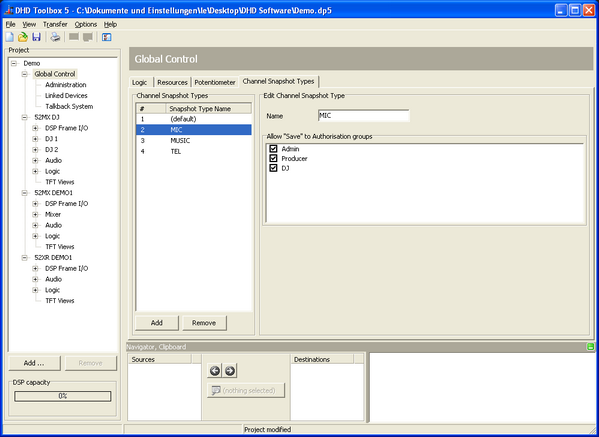
In the Channel Snapshot Types area you can see all channel snapshot types in a list. With the Add button below you can create up to 20 channel snapshot types. Click Remove to delete the selected entry from the list. A default type is automatically created. You are able to change the label and the settings of this default type, but it is not possible to delete this first entry of the list.
In the Edit Channel Snapshot Type area you can enter a label for the selected entry in the Name box.
In the Allow “Save” to Authorisation groups area all defined authorisation groups are shown (see Authorisation - Authorisation Groups). Select the check boxes in front of these labels to allow the users to save channel snapshots of fader channels with the respective type.
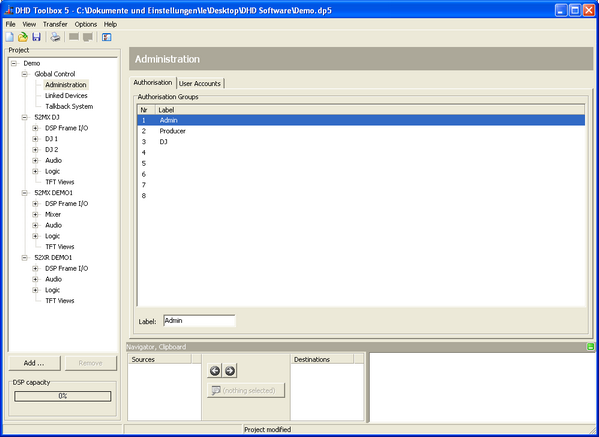
Administration
If you want to limit access to certain functions, you have to create authorisation groups. You should also create user accounts and assign the users to the authorisation groups.
In the project tree under Global Control, select the sub section Administration to edit the user rights.
Authorisation groups
In the Authorisation tab you can see a list, which shows a maximum of 8 possible authorisation groups that are marked by a serial number Nr. Authorisation groups can neither be added nor deleted. You can type a name for each group in the Label box below the list.
User Accounts
Click on the User Accounts tab to create user accounts and assign them to authorisation groups. With the Add User button in the User List area you can create up to 20 users. Click Remove User to delete the selected user from the list.
In the Edit User area, you can change several user settings. Enter a name of a user in the User Name box. Select the Display User Name check box to show the name of the logged in user in all displays of the control modules.
For all users, you can add a four-digit PIN code in the Personal PIN box. By entering the PIN code, the user has access to functions that are enabled for his user group.
You can log out the users automatically after a defined duration. After this duration the user has to log in again. Choose this duration from the Autolock drop-down menu. You can select 2, 5, 10, 15, 20 or 30 minutes or select Off to disable this feature.
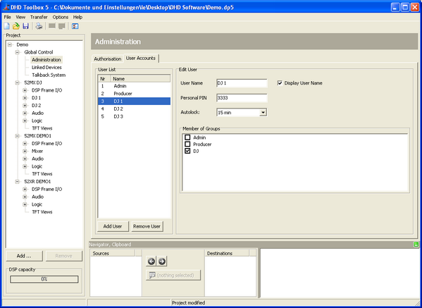
In the Member of Groups area, you can see all configured authorisation groups. Select the check boxes in front of the group names to assign the currently selected user to one or more authorisation groups. (see also Authorisation - Authorisation Groups, Authorisation - PIN Input Conditions and Authorisation - Limiting Access to Keys)
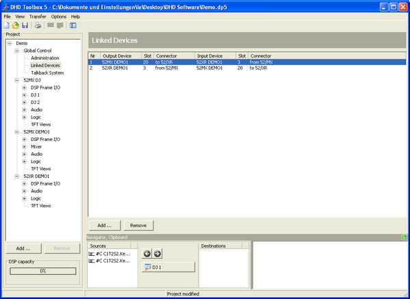
Linked devices
To simplify the audio configuration of connected devices within a project, you can connect them using device links. The labels for the audio channels have then to be entered for one of the two devices only - at the outputs. The inputs - assigned accordingly - automatically contain the same labels. (See also DSP Frame I/O - Configuring the DSP Frame / I/O Overview) If audio modules are linked via device links, label entries at the inputs are ignored. Besides the labels, the features Mono/Stereo and Headroom are linked.
To be able to use device links, at least two devices in the project have to be configured.
Note
The configuration of device links only exists to make work easier. There is no special function to this apart from the linked editing of labels and characteristics.
Device links can be generated for all available audio signals of the same type, for example from MADI to MADI, from digital AES3/EBU to digital AES3/EBU and from analog to analog. A device link is a link between a source and its destination, which both are defined using the number of a certain slot of the DSP frame. This is especially helpful with MADI links between devices. These are mostly used bidirectional.
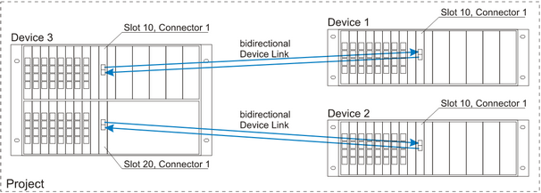
To set up a device link, do the following:
- Check whether the desired modules are a part of the configuration and if the appropriate features are set up. (See DSP Frame I/O - Configuring the DSP Frame)
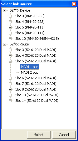
- In the project tree, select
Global Control/Linked Devices. - Use the
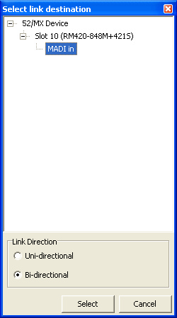
Addcommand from the contextual menu or clickAddunder theLinked Deviceslist to set up a new device link. A window opens, containing the slots and signals available in the project. - Select the desired signal source and click Select or double-click the source. The window with the signal sources closes, a window with the available destinations for the device link opens.
- Now, select the link destination in the same way you have selected the source. In addition, for MADI connections click Bi-directional, this way, both device links belonging together are created at the same time.
The device link is created and shown in the Linked Devices list. If there were problems with assigning, the appropriate error message is shown.
Tip
If you want to change a device link later on, you first have to delete it; then set it up new. For deleting, either use the Remove command from the contextual menu or click Remove.
Talkback system
The Talkback System subsection contains the tabs Talkback Member Matrix and Talkback Options. The options of these tabs are explained in the following sections.
Talkback member matrix
Use the talkback matrix to define which sources and destinations can communicate with each other.
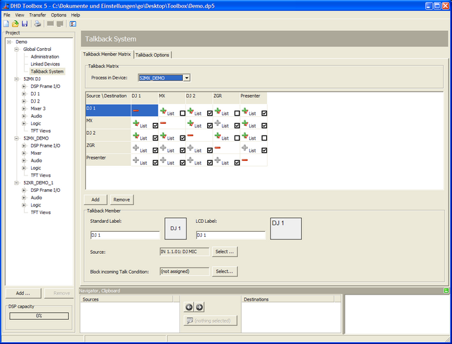
Click Add to add a new source and a destination to the matrix. Click Remove to delete a selected source and destination from the matrix.
In the drop-down menu Process in Device, select a device which processes the audio and logic resources for the Talkback matrix. If (none) is selected, the talkback matrix is not processed.
Click on the coupling points (plus and minus signs) in the matrix to set up a connection or to interrupt it (plus = connected, minus = not connected). This coupling point configuration allows intercom stations to globally communicate with each other. Connections in the matrix are shown as grey plus signs for now. The activation of the connection itself must be configured using key functions (see Control Modules/Talkback Functions) in the corresponding intercom stations or by directly dragging and dropping members from the Unassigned Talkback Members area (see Setting up Module Options/Unassigned Talkback Members) to keys. Assigned connections are shown as green plus signs with a red check mark. Next to the coupling points you see a List check box. Select this check box to define the Members of the talkback list. Use the key functions Talkback List and TalkToListMember to talk to a preselected member of this list (see Control Modules/Talkback Functions).
In the Talkback Member area, you can edit the names of the sources and destinations in the matrix by entering the appropriate name in the Standard Label box. For output on a LCD, you can type a special name in the LCD Label box.
You can assign an audio source for each talkback member. The user can use this audio source to talk into the matrix.
Select the desired source in the matrix and click Select at the Source box. The Audio Sources window opens. Click Assign to assign the source; alternatively double-click on the source or use drag & drop.
Note
Because of the structure of the matrix, several intercom stations can talk independently at the same time or communicate with each other.

You can define a logic function which blocks the incoming talk requests. Click Select at the Block incoming Talk Condition box, the Logic Sources window opens. Now select your desired function by drag & drop or double-click. Now a Prio check box is shown next to the plus signs of this talk member. Select this check box to allow a talk member to talk into a blocked source.
Talkback options
In this tab, you can set up further options for the talkback matrix.
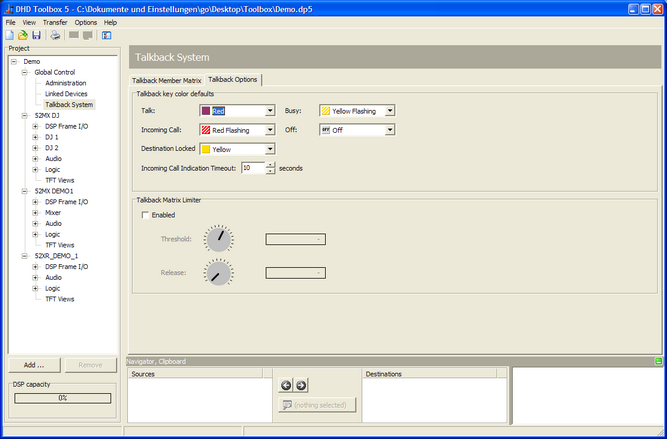
| Area | Option | Description |
|---|---|---|
| Talkback key color defaults | Talk | Select the color of the key that indicates that you are talking. (Colors available: red, red flashing, yellow, yellow flashing or off - no signaling.) |
| Busy | Select the color of the key that indicates that the connection to a participant is already taken by someone else. (Colors available: red, red flashing, yellow, yellow flashing or off - no signaling.) | |
| Incoming Call | Select the color of the key that indicates that a participant wants to open a connection with you. (Colors available: red, red flashing, yellow, yellow flashing or off - no signaling.) | |
| Off | Select the color of the key that indicates that there is no talkback connection active at the moment. (Colors available: red, red flashing, yellow, yellow flashing or off - no signaling.) | |
| Destination Locked | Select the color of the key that indicates that the participant, which are you trying to reach is locked (by a blocking condition). (Colors available: red, red flashing, yellow, yellow flashing or off - no signaling.) | |
| Incoming Call Indication Timeout | If a participant has tried to open a talk with you, this is indicated for a certain period by a lighting connection key. After that, this indication finishes automatically. The possible values are between 0 and 100 seconds. In case of a 0 seconds setting, the attempt is not indicated. | |
| Talkback Matrix Limiter | Enabled | Switch on this check box to enable the limiter for the input signals of the talkback matrix. |
| Threshold | Set the threshold for activating the limiter. | |
| Release | Set a value for the release time of the limiter. |