Fader Channels
In the project tree, you can find under <Device>/<Mixer> the subsection Fader Channels.
In this subsection you can configure the fader channels which are processed in the device. You can create up to 150 fader channels per 52/XC/XS device and 250 fader channels per 52/XD device. Each fader channels assigned audio source and further properties can be configured here.
Note
To be able to assign an audio source to a fader, it has to be defined as a fader channel first. After that, you can assign the defined fader channels to the faders using the Channel Assignment subsection in the project tree. (See also Channel Assignment)

You can use all audio signals available on the TDM bus as sources, in most cases input signals are assigned.
To create a new fader channel and assign an input signal to this fader channel follow these steps:
- In the
Defined Channelsarea, clickAddto create a fader channel. - In the
Generalarea, clickSelect, theAudio Sourceswindow opens. - In the
Audio Sourceswindow, select a source and clickAssign. Alternatively you can double-click on the source or drag it to theSourcebox. The source is now assigned to a fader channel.
If necessary, you can assign a single source to several fader channels.
Group Fader
To create a group fader, assign a program bus to the fader channel.
VCA Group fader
To create a VCA group fader, assign the desired VCA fader (1…8) from the Audio Sources window to a fader channel.
MIDI Fader
In addition, there are 16 MIDI sources without an audio signal. These are used to remotely control certain editing systems using the fader.
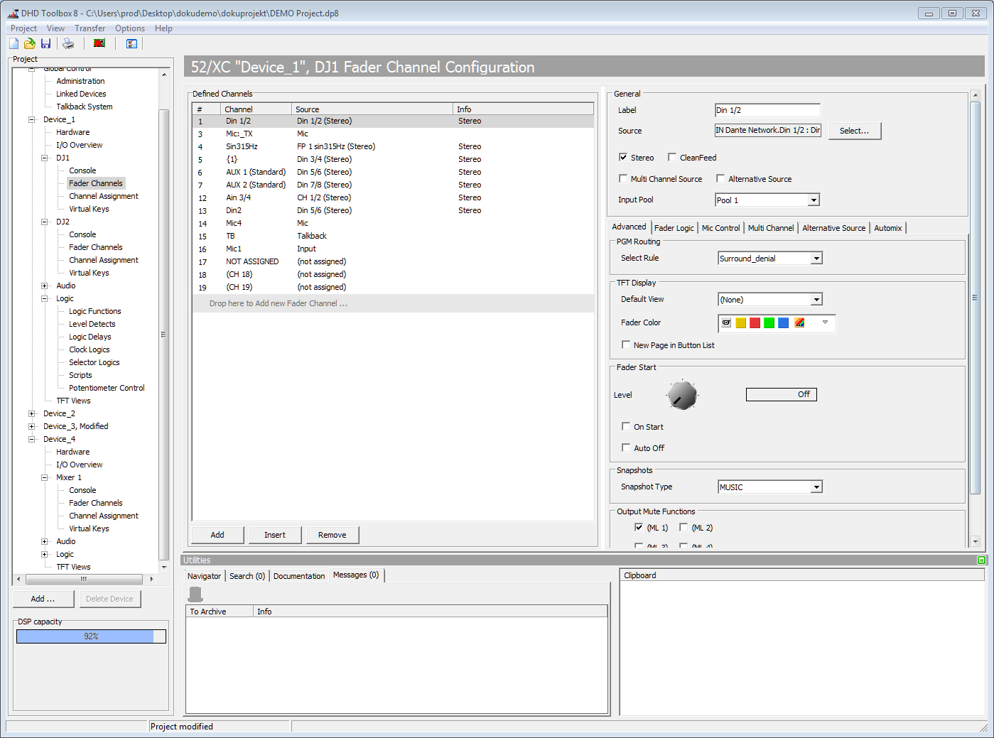
Defined Channels

In the Defined Channels area, you can create new fader channels and modify the existing ones. The list shows the defined channels. In the Nr (#) column, you see the serial number of the fader channel. The name of the channel is shown in the Channel column. The shown number of a channel is for information only, it has no meaning for the configuration.
In the Source column, the assigned audio source is shown.
You can decide, which information is shown in the next column. To see other information than default, press and hold Strg on your keyboard. All selectable parameters will now be displayed blue on the right hand side. Select by clicking on the text, which parameter you want to be seen. This is useful to become a quick overview on input pool assignment, multi channel source state, default TFT view…
The sequence of the fader channels in the list is identical with the sequence, in which the channels are saved in the assigned input pools. If several input pools are used, the sequence runs from top to bottom separately for each input pool. If you want to change the sequence of the list entries, you can drag a fader channel to the new position.
To create a new fader channel, click Add.
To insert a new fader channel above a selected list entry, click Insert.
To delete a fader channel, select it in the list and click Remove.
General
In the General area, you can configure the following general options for a fader channel:
| option | description |
|---|---|
| Source | • Shows the audio signals (mono or stereo) that are used as input for the fader channel. You can edit the source of an already created fader channel by double-clicking on the selected fader channel in the list or by clicking Select. You can also drag a source from the Audio Sources window to the Source box. |
| Label | • Name of the channel. When first assigning an input to a new fader channel, the first 16 digits of the audio sources name are automatically taken over. The name can be changed later, by typing a new name in the Label box. |
| Stereo | • The channel is mono or stereo. The mono or stereo characteristics is adopted automatically from the assigned source. It can be modified later on by selecting or clearing the Stereo check box. NoteYou can assign only consecutive channels as stereo sources (beginning with the left one). |
| Multi Channel Source | • Please see Surround Configuration for more information on this function. |
| Clean Feed | • This check box assigns a corresponding clean feed signal (n-1) to the channel. Please note that the summing bus is used as a resource and inserted in the Available Busses list under <Device>/<Mixer>. (See also Mixing Functions – Configuring Internal Busses)• Clean feeds are always assigned to one fader channel within a DHD device. If this assignment is not intended, you can use Aux or program busses for creating clean feed signals. |
| Alternative Source | • Enables Alternative Source Input selection on Alternative Source tab below. |
| Input Pool | • You can assign a fader channel to one input pool. To do this, select an input pool in the Input Pool list. In this list only the input pools are shown, which are configured under Audio on the Input Pools tab. Use None to permanently assign a fader channel to a fader.• If you do not want to use a fader channel in an input pool, but do not want to remove it either, you also should assign None here. (See also Input Pools) |
Advanced
On the Advanced tab, you can configure the following options for the currently selected channel:
| area | option | description |
|---|---|---|
| PGM Routing | Select rule | • Select a program routing rule from the list. (See PGM Routing Rules) |
| TFT Display | Default View | • Select a fader view that is shown as long as no other view is selected. If you configured a Default View, this is automatically preset, but can be replaced by a different fader view. (See also TFT view creation) |
| Fader Color | • Select a Color for corresponding TFT fader element. | |
| New Page in Button List | • Creates a new page in an input select button list. | |
| Fader Start | • The fader starts can be used as logic source for any function. They are routed directly to the GPOs or linked by a logic function, for example as On Air signal. Note If you route a fader start to a GPO, when configuring the GPO, you have to decide whether the controlling signal should be created as level change (Level) or pulse (Start/Stop Pulse). |
|
| Faderstart Level | • When the fader is above the selected level, the fader start function (logic source: Faderstart/FS <faderchname>) is enabled. OFF is preset, for example the bottom stop of the fader. You can define the level in a range between OFF and -10 dB in steps of 10 dB. The setting refers to the scale in the fader strip. |
|
| On Start | • The logic source Faderstart/FS <faderchname> is only activated using the Channel On/Off key function, not when moving the fader. NoteIn this case, in the fader module, the corresponding key function must be defined: either as combined function Channel ON/OFF or as two functions Channel ON and Channel OFF. |
|
| Auto Off | • By closing the fader, the channel is automatically switched OFF. NoteIn this case, in the fader module, the corresponding key function must be defined: either as combined function Channel ON/OFF or as two functions Channel ON and Channel OFF. |
|
| Snapshots | Snapshot Type | • Select a channel snapshot type from the list to assign it to the fader channel. |
| Output Mute Functions | Mute Logic 1…5 | • Here, you can define which mute logics are enabled when opening a fader. Mostly, this assignment is used to mute speakers when opening microphone channels. You can control up to five mute logics. To do this, select the corresponding check boxes. • You can change the names of the different mute logic paths under Audio in the project tree, on the Mute Logics tab. (See Configuring Mute Logics) • You assign the corresponding mute logics to the output signals of an DHD device under Audio/Output Routing in the project tree. |
Fader Logic
On the Fader Logic tab, you define how the selected fader channel is linked to the logic system of the DHD device. You can configure the following options:
Logic Sources
| option | description |
|---|---|
| Ready Signalisation | • Here you can define, which logic source makes the display that the channel is ready lighting up. State can be shown in ON/OFF Buttons. As default, the logic source is set to Channel OFF. In this case, the display lights up when the fader is closed or switched off. If you want READY never to light up, select (none).• To change the logic source, click Select, the Logic Sources window opens. Select the desired logic source and click Assign. Alternatively, you can double-click on the logic source or drag the logic source to the Source box.• Examples: You can use a GPI to show status signals of the input devices. Or a presenter can show signals in the microphone channel, when he pushes external keys, which are connected by GPIs. |
| Mute Condition | • You can select the logic source which triggers a muting of the fader channel. When muting is active, the audio signal is not sent to PGM, AUX or Clean Feed busses. PFL is still possible. • The default value is (not assigned), the channel is not muted.• To change the logic source, click Select, the Logic Sources window opens. Select the desired logic source and click Assign. Alternatively, you can double-click on the logic source or drag the logic source to the Source box.• Examples: You can connect, external muting keys by GPIs. Important An incorrectly assigned logic source can cause a permanent muting of the fader channel! |
| Fader Function 1 Lamp Source | • If you have assigned the Fader Function key function to a key of a fader module, here you can select a logic source which causes the LED of this key to light up.• The default logic source is the fader function of the selected fader channel itself (Fader Function/FF <Faderchname>). In this case, the key is lighting up when the fader function is active. • To change the logic source, click Select, the Logic Sources window opens. Select the desired logic source and click Assign. Alternatively, you can double-click on the logic source or drag the logic source to the Source box. • Examples: As talk key for clean feeds or as talk key for headphones, which are assigned to certain microphones (configuration via output functions), fader start on/off for play-out devices (configuration via logic function). |
| Fader Function 2 Lamp Source | • Function identical with Fader Function 1 Lamp Source. |
| Channel On Logic | • Select a logic source, which switches the fader channel to the ON state.• To change the logic source, click Select, the Logic Sources window opens. Select the desired logic source and click Assign. Alternatively, you can double-click on the logic source or drag the logic source to the Source box. |
| Channel Off Logic | • Select a logic source, which switches the fader channel to the OFF state.• To change the logic source, click Select, the Logic Sources window opens. Select the desired logic source and click Assign. Alternatively, you can double-click on the logic source or drag the logic source to the Source box. |
| Voice On Logic | • Select a logic source, which routes the fader channel to the internal voice bus. • To change the logic source, click Select, the Logic Sources window opens. Select the desired logic source and click Assign. Alternatively, you can double-click on the logic source or drag the logic source to the Source box. |
| Voice Off Logic | • Select a logic source, which removes the fader channel from the internal voice bus. • To change the logic source, click Select, the Logic Sources window opens. Select the desired logic source and click Assign. Alternatively, you can double-click on the logic source or drag the logic source to the Source box. |
Logic Control
| option | description |
|---|---|
| Timer Reset | • If set, timers 1…5 will be reset and started when opening the fader. Timer 6 is not initialised. • If you have configured a key in a fader module with the Timer Functions/Timer Fader key function, you can turn the function on/off for each timer. Timer 6 can also be activated.• To disable, create 5 virtual keys with the Timer Functions/Timer Fader key function. Make sure they are set off. |
| Voice | • If this check box is selected, the fader channel enables the logic source <Mixer>/Mixer Functions/<Mixer>:<Mixer>.Voice.• The fader channel is routed to the voice bus, by default. • Example: You can assign the logic source Voice to a GPO, thus using it as external speech/music indication. |
| PGM1 Logic | • If this check box is selected, the fader channel enables the logic source <Mixer>/Mixer Functions/<Mixer>:<Mixer>.PGM1, but only if the channel is routed to program bus 1 at the same time. • Example: The logic source PGM1 Logic can be used as Air Check Record Start via GPO - only open faders routed to program bus 1 and with this function configured start the recording. |
| Auto OffAir | • If in a fader module you have configured an Auto OffAir key, all channels with selected Auto OffAir check box are switched to Off-Air mode when pressing this key. |
| Auto PFL | • If in a fader module you have configured an Auto PFL key, all channels with selected Auto PFL check box are switched to PFL mode when pressing this key. |
| Solo Effect Return | • The channel is not muted if the Solo In Place function is active. |
| Activate Fader Function 1 | • If this check box is selected, the logic Fader Function 1 (Channel)/<Mixer>.FF1 Ch 1…n can be activated. |
| Activate Fader Function 2 | • If this check box is selected, the logic Fader Function 2 (Channel)/<Mixer>.FF2 Ch 1…n can be activated. |
| Fader Function 1 Reset | • Opening the fader deactivates the logic Fader Function 1 (Channel)/<Mixer>.FF1 Ch 1…n. |
| Fader Function 2 Reset | • Opening the fader deactivates the logic Fader Function 2 (Channel)/<Mixer>.FF2 Ch 1…n. |
| Freeze AGC / Loudness AGC when Fader Start OFF | • A closed fader will pause the AGC or Loudness AGC. • No new gain values will be set. The current gain value will stay set until the fader is opened. |
Combined Logic Default Assignment
| option | description |
|---|---|
| Combined Logic 1…4 | • Select these check boxes to enable a Combined Logic for this fader channel by default. |
Mic Control
On the Mic Control tab, you can configure the microphone preamp options for the currently selected fader channel:
PreAmp Source and Control
Note
These options are usually used to control microphone inputs, which are installed in a linked device.
| option | description |
|---|---|
| Mic Input | • Select the hardware input which you want to control (analog gain and phantom power). • This is only possible for Mic/Line Inputs. |
| Control Condition | • Select a logic source which enables the controlling of analog gain and phantom power values. You should select a control condition, because these options are globally valid for all recipients of the signal. Make sure, that at any time, it is defined which user currently has the right to change values. |
PreAmp default values
| option | description |
|---|---|
| Analog Gain | • Set the default value for analog gain, for this fader channel. Note Some analogue I/O cards do not provide all gain values. |
| P48V | • Select this check box to enable phantom power for this fader channel by default. |
Multi Channel
This Function enhances the Workflow for 5.1 Mixing. For further information see (Surround Configuration)
Alternative Source
Alternative Source adds possibility to switch quickly between two sources on the same Fader Channel. All settings on the Fader Channel remain the same. With an input select on a physical fader you change the assigned fader channel and all parameters.
Activate Alternative Source check box, then go to Alternative Source Tab. Select the source and enter a distinctive name in the Label box. This label will be shown on Channel displays. Now, you can define an Alternative Source Button on your Console or View (Key-Function: <Channel Function>/On/Off-Functions/Alternative Source, see Alternative Source Key function). When pressing the Button, the source is switched. This is useful, for example for telephone hybrids or audio codecs.
Important
The button to switch between Source and Alternative Source has no On-Air protection. Consider restricting access to avoid accidents.
Automix
You can set default Automix options for that fader channel.
| Option | Description |
|---|---|
| Enable | Activates the Automix function on the selected channel. |
| Passive | Activates the Passive Mode on the selected channel. This channel does not have any effect on the other channels of the same Automix Group. Passive channels are ducked by active channels. |
| Default Group | Assigns the fader channel to one of the three available Automix groups. |
| Weight | Changes the level that is sent to the Automix detection. Higher values increase the sensitivity. Lower values lead to a constant ducking effect. Changing the Weight is finally equivalent to changing the fader position. Values between -20dB and 20dB possible. |
Tip
For more information see Automix page.