Channel Assignment - Assigning Fader Channels and DSP Processing
In this subsection, you can assign the fader channels to the physical faders of the configured fader modules. Apart from that, in this window you can configure the signal processing for the input signals (input DSP processing).
Important
You should assign at least one fader channel to every physical fader.
If not, the physical fader is not included in the DSP processing. During operation, you can not assign a fader channel to a physical fader, which has not assigned any fader channel.
If you wouldn't want to assign an input to a physical fader, for example in your Setup 0, but want to assign a fader channel to this physical fader by using the Access key at the console, follow these steps:
1. In the project tree, select <Device>/<Mixer>/Fader Channels.
2. Create a fader channel and do not assign a source. (See Fader Channels)
3. In the General area, enter a name in the Label box, for example NOT ASSIGNED.
4. In the input pool list, select the desired input pool for this fader channel. (For creation of input pools see Input Pools)
5. In the project tree, select <Device>/<Mixer>/Channel Assignment.
6. Assign this fader channel to the desired physical fader.
You can assign each fader channel to a physical fader as long as you don't exceed the maximum number of faders. If you have configured a key on the console to toggle between Layer A and Layer B, you can use this key to toggle between the primary and secondary function for all physical faders with two configured layers.
Important
You can configure a maximum of 64 faders in a maximum of 4 layers (52/XD, 52/XD2)!
Example: On a console with 40 fader modules, all available fader modules are assigned fader channels in Layer A. This way, in Layer B 24 of the 40 fader modules can be assigned as a second fader channel.
Maximum amount of fader and layer depends on your core. Please note your Functional Range of the XC2/XD2/XS2 Core Devices with Firmware 9.1 and 9.2!
You can access the settings for both layers by selecting the Layer A…D tabs. The available settings are identical for all layers.
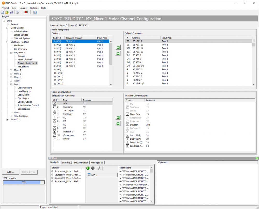
Fader Assignment
The faders of the console are numbered 1…X. If the module IDs are consecutively defined from left to right, the left fader in the console is number 1, the fader to the right is number 2, and so on.
The Fader Assignment area contains two lists: the Faders list and the Defined Channels list. In the Faders list, the physical faders that are available are shown. The number of faders shown in the Faders list depends on the total number of configured fader modules (see Console configuration). In the Defined Channels list, the available fader channels are shown.
To assign a fader channel to a physical fader, follow these steps:
- In the
Faderslist, select a physical fader. - In the
Defined Channelslist, double-click on the fader channel which you want to assign. Alternatively, you can select a fader channel and click , or drag a fader channel from the
 Defined Channelslist to the desired physical fader in theFaderslist.
After the assignment, the assigned fader channel disappears from the Defined Channels list because it isn't available for assignment anymore.
To remove an assignment, select the physical fader in the Faders list and click ![]() . Alternatively, you can drag the assigned channel from the
. Alternatively, you can drag the assigned channel from the Faders list to the Defined Channel list.
In the Faders list, you can exchange the assignment of two physical faders by dragging an assignment from one fader to another fader.
Important
If working with input pools, you should mind the following:
• The sequence of entries in the Faders list determines the fader assignment after loading the Config to the device. To change the sequence of the fader channels for the Input Select function (by a rotary controller) change the sequence of the fader channels in the Defined Channels list under <Device>/<Mixer>/Fader Channels. (See also Fader Channels)
• At least one channel per input pool has to remain in the Defined Channels list to be able to execute the Input Select function.
•You can assign one input pool to a fader or link the faders permanently to a fader channel that is not part of the input pool. This way, you can create a so-called fixed fader. However, you can not put one fader into more than one input pool.
Fader Configuration
In the Fader Configuration area, you can select the input DSP Processing for each fader. This processing is done before the fader changes the signal level (Pre fader).
Number, type and sequence of the corresponding DSP functions can be defined separately for each fader - except the faders that are assigned to input pools.
Important
For input pools, the input DSP processing is assigned to the pool itself - not to the separate faders. This means, that all faders with the same input pool have identical signal processing for input signals! Therefore, you have to configure them only once, it is then automatically and simultaneously changed for faders assigned to the same input pool.
To modify the input DSP processing of a fader, follow these steps:
- In the
Fader Assignmentarea, in theFaderslist, select a fader with an already assigned fader channel. - In the
Fader Configurationarea, in the Available DSP Functions list, select the desired DSP function. - Click to assign the DSP function to the selected fader. Alternatively, you can double-click the desired DSP function or drag it from the Available DSP Functions list to the
Selected DSP Functionslist to assign it to the fader.
All assigned DSP functions for one selected fader are shown in the Selected DSP Functions list.
To remove a signal processing from the Selected DSP Functions list, select the DSP function in this list and click ![]() . You can also double-click on the DSP function or drag it from the
. You can also double-click on the DSP function or drag it from the Selected DSP Functions list to the Available DSP Functions list.
Note
The DSP functions are processed in the order which they are sorted in from the top to the bottom of the Selected DSP Functions list. You can change this order using drag & drop.
Available DSP Functions
The following DSP functions can be used for the input processing:
| available DSP functions | max. number per input channel DSP processing | option/parameter |
|---|---|---|
| Limiter | 1 | 1. Threshold: Threshold in the range -20 dBint to +20 dBint (in steps of 1 dB). 2. Release Time: Release time in the range 3 dB/s to 20 dB/s (in steps of 1 dB/s). • The attack time can not be adjusted, it is always set to quick. |
| Compressor | 1 | 1. Gain: Output gain in the range of 0 dB to +30 dB (in steps of 1 dB). 2. Threshold.: Threshold in the range -50 dBint to +10 dBint (in steps of 1 dB). 3. Ratio: Ratio in the range of 1.0:1 to 5.0:1 (steps of 0.1). 4. Attack: Attack time in the range of 0.2 ms to 50 ms (8 values). 5. Release: Release time in the range of 0.05 s to 10 s (8 values). |
| Expander | 1 | 1. Gain: Output gain in the range of 0 dB to +30 dB (in steps of 1 dB). 2. Threshold.: Threshold in the range -50 dBint to +10 dBint (in steps of 1 dB). 3. Ratio: Ratio in the range of 1:1.0 to 1:5.0 (steps of 0.1). 4. Attack: Attack time in the range of 0.2 ms to 50 ms (8 values). 5. Release: Release time in the range of 0.05 s to 10 s (8 values). |
| EQ | 4 | • Equalizer with up to 4 bands. 1. EQ Type: EQ type can be toggled between Bell, Notch, Shelving High and Shelving Low. 2. Gain: Gain in the range -15 dB to +15 dB (in steps of 0.25 dB). Option is ignored if EQ type Notch is selected. 3. Frequency: Frequency in the range 22 Hz to 20000 Hz (60 fixed preset values). 4. Quality: Quality in the range 0.1 octaves to 3.0 octaves (in steps of 0.1 octaves). Option is ignored if EQ type Shelving Low/High is selected. • The toggling of the EQ type is not noiseless! |
| Sub Sonic | 1 | 1. Frequency: Frequency in the range 22 Hz to 20000 Hz (61 fixed preset values). • This subsonic filter is a 3rd order high pass filter (18 dB/octave). For other filter orders, please use the function Var. LP/HP. |
| DeEsser | 1 | 1. Ratio: Ratio in the range 1.0:1 to 4.0:1 (in steps of 0.1). 2. Threshold: Threshold in the range 1.0 to 1.8 (in steps of 0.1). 3. Bandwidth: Bandwidth in the range 0.2 to 0.5 (in steps of 0.1). Important High system requiremens! Recommended: Use DeEsser2 if not enough resources available or to save DSP capacity. |
| DeEsser 2 | 1 | 1. Frequency: Frequency in the range 1000 Hz to 20000 Hz (28 fixed preset values). 2. Threshold: Threshold in the range -40 dB to +10 dB (in steps of 1 dB). |
| Noise Gate | 1 | 1. Attenuation.: Attenuation in the range 0 dB to 30 dB (in steps of 1 dB). 2. Threshold: Threshold in the range -60 dBint to -10 dBint (in steps of 1 dB). 3. Attack: Attack time in the range of 1.0 ms to 200 ms (8 values). 4. Release: Release time in the range of 0.01 s to 2.0 s (8 values). |
| Var. LP/HP | 2 | • Variable filter, high pass or low pass up to 10th order. 1. Filter Type: Filter type can be toggled between HighPass and LowPass. 2. Frequency: Frequency in the range 22 Hz to 20000 Hz (60 fixed preset values). 3. Filter Order: Filter order can be set between 1st order (6 dB/octave) and 10th order (60 dB/octave). • The toggling of the type and filter order is not noiseless! |
| Delay 1s | 1 | 1. Delay time: Adjustable between 0 s and 1 s in steps of 1 ms. |
| Delay 10 s | 1 | 1. Delay time: Adjustable between 0 s and 10 s in steps of 1 ms. |
| AGC (Automatic Gain Control) | 1 | 1. Velocity: Control speed in the range 0.3 dB/s to 6.0 dB/s (in steps of 0.1 dB/s). 2. Gain: Max. signal shift in the range 0 dB to 30 dB (in steps of 1 dB). 3. Level: Set output level in the range -20 dBint to 20 dBint (in steps of 1 dB). 4. Threshold: Freeze threshold of the AGC in the range -40 dBint to -20 dBint (in steps of 1 dB), for lower levels, the current or last value is recorded respectively. |
| Loudness AGC | 1 | • Automatic Gain Control, triggered by loudness 1. Velocity: Control speed in the range 0.1 LU/s to 6.0 LU/s (in steps of 0.1 dB/s). 2. Gain: Max. signal shift in the range 0 dB to 30 dB (in steps of 1 dB). 3. Level: Set output level in the range -20 LU to 20 LU (in steps of 1 LU). 4. Threshold: Freeze threshold of the Loudness AGC in the range -60 LU to 0 LU (in steps of 1 LU), for lower levels, the current or last value is recorded respectively. |
Important
The configuration of the Input DSP Processing requires computing power depending on the number of configured faders! Not all combinations are possible, especially when using the Deesser function. Therefore, mind the DSP capacity bar below the project tree during the configuration.