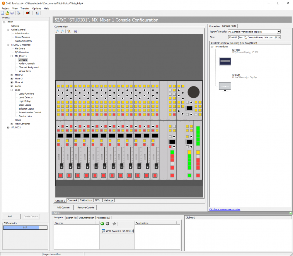
Console
For each device there is in the project tree a Console subsection under the <Mixer> node. To configure the user interface of the console, select this subsection.
In the Console View area, you can configure the console layout and select keys for assigning key functions.
On the right hand side, you have two tabs: Properties and Console Parts.
Console Layout Configuration
To create a new console, click Add Console below the Console View area. A new Console <X> tab will be created. You can create up to 14 consoles per mixer.
To remove a console, in the Console View area, select the console that should be removed and right-click on the console tab. Select Remove Console from the contextual menu. Alternatively you can click the Remove Console button below the Console View area.
To rename a console, in the Console View area, right-click on the console tab you want to rename. Select Rename Console from the contextual menu. A Rename Console window opens. Enter the new console name in the New Label box. Click OK.
Console Parts
Go to Console Parts tab on the right hand side. Select your preferred Type of Console from the list. Standard value is (Auto). You can also select the Size of your console, by selecting a specific console frame size from the list. When changing console type, size selection will also change.
Start creating your console layout by drag & drop your modules from the Available Parts for mounting list to the Console View.
When dragging the first module to the console view, the view editor selects automatically the type of your console and the size of installation frame. The Available parts for mounting list will now only show parts for your installation frame size. Selection of other modules than the selected type is now disabled. You can now start to drag & drop modules in the frame.
To remove a module, in the Console Layout area, right-click on the module you want to remove. Select Delete Module from the contextual menu.
Note
If you have different console types or frame sizes, create multiple consoles.
Tip
For full module lists, see https://dhd-audio.com
Console View - Contextual Menu
Assignment
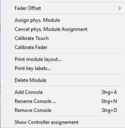
In the contextual menu of a module, you find the function Assign phys. Module. Use this function to match your console layout to the physical console. This assignment defines which hardware module corresponds to which configured software module.
You have to do this assignment for each each module, module group (controller in 52/MX) as well as for each TFT display. If your module needs to be assigned, displays will show NOT ASSIGNED. TFTs will remain blank if not assigned.
Important
Before executing this command make sure:
- The core is switched on and has network access.
- The core has the current configuration from toolbox.
After clicking Assign phys. Module, the selected module or a group of modules start flashing in the console layout. At the same time, at least one key flashes on each available module of the physical console and ASSIGN buttons are shown on the TFT displays. Now press any key on the module or the ASSIGN button on the TFT display that you want to match to the software module from where you called the Assign physical Module command. This way, the function is automatically terminated and you have assigned the selected graphical module to the corresponding hardware.
To cancel the assignment procedure right-click on an module in the console layout and select Cancel phys. Module Assignment.
Calibrate
In the contextual menu of a module you can find a Calibrate command.
Use the Calibrate command to adjust the 0 dB fader positions and to appoint the touch sensitive area of TFT displays.
Important
Calibration command executes directly and without response of the module. For fader modules, bring all faders to 0 first. Then use the command. If the fader values are out of tolerance, they will not be calibrated.
Calibrating faders
Set all faders of a fader module to 0 dB (as accurately as possible). Right-click the respective module in the console layout and select Calibrate from the contextual menu. Now, all faders of this module are set to the new value. Repeat this procedure for all other fader modules.
Calibrating TFT displays
Right-click the desired TFT display in the console layout and choose Calibrate in the contextual menu. Now, you can see a cross in one of the physical TFT displays corners. Press this cross as accurately as possible and do the same for the crosses that will appear in the other corners of the display. Repeat this procedure for all other TFT displays.
Warning
Use the Calibrate command only when really necessary.
Module Mode
In the contextual menu of a selected module, the command Module Mode is useful for overbridge modules. Here you can select the assigned fader for the Module. For TFTs with fader views, it is the starting (first) fader.
Printing
In the contextual menu of a selected module, you find the commands Print module layout and Print key labels. Use them to either print the complete module view including the assigned labels or just the key labels.
Show Controller Assignment
Show Controller Assignment is also available with the ![]() icon. It shows misconfiguration of modules on MX frames. Modules marked yellow are not connected to default controller port. Modules marked red are not connected. To change connection on the controller unit and port, select
icon. It shows misconfiguration of modules on MX frames. Modules marked yellow are not connected to default controller port. Modules marked red are not connected. To change connection on the controller unit and port, select Properties Tab. On Controller Unit menu, you can set unit and port the module is connected.
Important
MX Modules are assigned automatically to ports on the controller unit. Only change the ports if necessary.
Toolbox assigns DSP resources for every inserted fader module automatically. These DSP resources are necessary for the input processing. One stereo processing is needed per fader. In this case, only empty DSP processings and the necessary routing channels are assigned to the bus system. If you assign specific DSP functions to the fader channel, the DSP load increases again.
Important
Your core must fit the requirements for your number of faders. See Functional Range of Series 52 Core devices or the Channel Assignment page for further information.
Properties
The Properties tab is used to edit module options or push-button configuration.
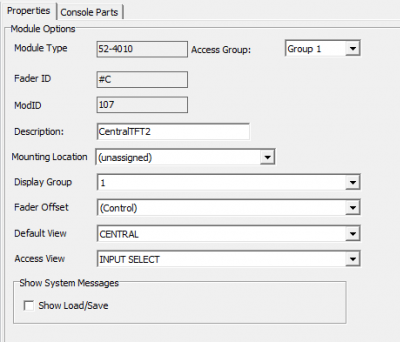
Module Options
If you select an entire module in the Console View area, it will be colored blue. The Properties tab shows all possible options on this module. Not all options are displayed and possible on all modules.
Module Type: Shows the name of the module. This value can not be changed.Access Group: Select to which access group the module should belong. All modules of the same access group cooperate for certain functions, for example when you create parameters for a fader channel on the central console. There are four access groups.Fader ID: Shows the automatically assigned Fader IDs of this module. This value can not be changed.ModID: Shows the automatically assigned Module ID of this module. This value can not be changed. The Module ID is for example required to configure the Control Link feature.Description: This description is shown in the displays of the control modules. The description should simplify the identification during the further configuration. The description overwrites the module ID. Type a space character in the description box to set the display to off by default.Select Variant: The selected module exists in different variants. Choose the correct variant in order to match the configuration with your hardware.
Dependent on the currentProduct Filterfor discontinued products (see Options Menu/Product Filter Tab) 52/MX console frames and 52/RX modules will provide a selection betweenRev. BandRev. Cvariant:
Rev. Bindicates that the selected console/module is equipped with a 52-4050 controller internally.Rev. C(standard variant) indicates that the selected console/module is equipped with a 52-4060 (APC based) controller internally.
Mounting Location: You can assign a mounting location, if you have created any.Display Group: Assign a TFT to a display group. When selecting a display group, pay attention if you have any Display Group Filters enabled. It is recommended to use a different TFT Group for every TFT connected to avoid unlikely effects.
Note
In Toolbox Version 9 you can use up to 20 differentCentral Diplaygroups.Fader Offset: Define the offset of your fader channels on your modules. Thereby all fader channels on the console(s) will appear in the correct order.Default View: Select a default view for the TFT. If you have more than one TFT in the same central display group, make sure to select the same default view everywhere to avoid unlikely effects.Access View: Select a default access view for the TFT.Show System Messages: Decide, if the TFT shows system messages, such as information, success, warning and error notifications.Display Options(it is required to select the OLED display in the module preview): The displays of the Series 52 fader modules are able to show four lines. In the table you can define which content is shown in the several lines. Click on the content of a line to open a list and select the desired content for each line. You can create different setups for single channels by activating the functionIndependent Displayfor these channels.Invert fader scale(fader modules only): Invert the faders of the whole mixer. To close a fader, you have to move it to the upper position. To open, you have to move it to the lower position.0 dB at fader max position(fader modules only): Shift the scale of all fader modules in a mixer by 10 dB, so the fader has an amplification of 0 dB on the top position. Please note that the labelling of the front plate can not reflect this shift, it remains unchanged.Fader Speed(52/MX, 52/RX fader modules only): Set the speed of motorised faders during automatic movements likeChannel Start ON/OFFor layer switching.Encoder Bus Range: Can be used for changing encoder functions via central keys. Assign an encoder bus to encoders and use the key functionEncoder Function Setto manipulate the encoders default function.Controller Unit(52/MX only): select if you connected modules different than default.
Key Configuration
You can assign the desired functions and labels to the fader and control modules.
To configure keys of fader and control modules, follow these steps:
- In the
Console Viewarea, click on the key, which you want to configure. On thePropertiestab the options for this key will be shown. - Enter a label for the key in the Text box. This label is used as printout for the label key caps. To use a forced line break in the key label, enter a backslash
\. - Click
Function…. TheKey Functionswindow opens. - Select the desired key function by double clicking. Also, you can drag it to the key preview on the
Propertiestab, or to the(No Function)text, or to the desired key in theConsole Viewarea. According to the selected key function, additional parameters for the configuration of the key appear on thePropertiestab.
The keys on the fader modules can be configured with the key functions for fader modules, independent from the position and layout of the keys. (See Key Functions - Fader Modules)
The keys on the control modules can be configured with the key functions for control modules, independent from the position and layout of the keys. (See Key Functions - Central Modules)
Key Colors
If you have assigned a key function to a key, always an area with color options appear on the Properties tab.
Set the logic sources which lead to the lighting conditions of the key.
Depending on the selected key function, you can define here with which color the key shall light up according to the lamp source. On is the color if the function is enabled, Off if the function is in inactive condition. For the last case, mostly the Off option is used, for example the key does not light up. Depending on the selected key function, you find also different names in the Lamp Source column, for example Standby, Available, Busy, Owned, Layer A, Layer B or the name of the selected lamp source.
For the small keys of the modules, you can define the colors red and yellow. The large keys can light up in red, yellow and green. You can define flashing colors for the keys. Select the ![]() check box, in the
check box, in the Colors area.
Note
For some large keys yellow is not available as an option. You can use a mixed color instead which corresponds with yellow. This is due to the fact that yellow is not generated by a separate LED but is a mix from red and green. Depending on the tolerance of the components, the key color can differ between the keys. Toolbox displays it als yellow option.
Authorisation - Limiting Access to Keys
You can assign authorisation groups to certain keys. Use these authorisation groups to deny a user group access to certain keys. You have to create the appropriate authorisation groups previously.
On the Authorisation tab, you see the modules of the console in a minimized view. Keys that have been assigned to an authorisation group are shown red, not assigned keys grey. All grey keys can be used by all console users without entering a PIN.
Important
You can limit access to keys if you have already set up authorisation groups.
To assign a key to authorisation groups, follow these steps:
- Select the key in the
Console Viewarea. - In the
Propertiestab, you can see aAuthorisationsection with authorisation group check boxes. Select the authorisation groups, which have access to that key. When clicking the icon on top of the
 Console Viewarea, keys with limited access will light up red.
Important
If you use keys of the console for enabling PIN entry, please make sure that no authorisation group is assigned for these keys, otherwise you can not log in at the console!
Unlock Condition
You can assign a logic condition to unlock the key or TFT button. The key action will only be handled if the unlock condition is true. Unlock condition can be e.g. another key, TFT button or a logic function. You can use this function to protect key functions vital for operation (e.g. routing actions) against accidental pushes.
Key Functions - TFT Views
On TFT views you can assign key functions to buttons. Depending on their purpose these buttons could be used for channel related functions or for central control related functions.
In the Key Functions window, below the functions list, you can select in the Filter tree as… area if you want to see the central functions (Central List) or channel related functions (Channel List).
Channel List
With the Channel List filter , you can see nearly all key functions, that are usually available for use on fader modules, see Key Functions - Fader Modules.
When using the key functions of fader channels on a central TFT or a central module, you must assign the channel, you want to act on. In the Act… area on the Element Configuration or Properties tab, you can define a Fader / Layer, a Channel or flexible assignment with access.
Central List
With the Central List filter, you can see nearly all key functions, that are usually available for use on central modules, see Key Functions - Central Modules.
Key Functions - Fader Modules
All functions that you can configure for fader modules and fader overbridge modules are described in this subsection.
Note
The configurable key functions for fader modules and control modules are different!
To basically configure a key, see Configuring keys of fader and control modules.
If you define a function for a key on a fader module, this function is assigned for the same key on all neighbour fader modules of the same type. If you change the function of a key, the appropriate keys of the other fader modules change as well. You can stop this coupled behaviour for each key. To do this, select the Independent Key check box on the Properties tab.
You can use the Independent Key option for example for a fader with statically assigned sources or if you want to physically offset a fader module, for example for an independent operator.
Depending on the function you choose for a key, on the Properties tab, additional options are shown.
In the following tables, you find all available Key Functions and their options or sub-functions.
The functions that can be assigned directly to the encoders of fader modules are identical to the options of the Encoder Function Set function.
(No Function)
| option or sub-function | selection | description |
|---|---|---|
| • no function, labeling for printout is possible |
Access Function
| option or sub-function | selection | description |
|---|---|---|
| Access | • Channel is put into Access Mode. |
Channel Functions
| option or sub-function | selection | description |
|---|---|---|
| Channel ON | • The channel is switched on. • By default, audio signal and fader start are enabled. In the Fader Channels subsection in the project tree, on the Advanced tab, you can set additional options (On Start, Auto Off and Level) in the Fader Start area. |
|
| Channel OFF | • The channel is switched off. • By default, audio signal and fader start are disabled. In the Fader Channels subsection in the project tree, on the Advanced tab, you can set additional options (On Start, Auto Off and Level) in the Fader Start area. |
|
| Channel ON/OFF | • The channel is toggled on and off using the same key. • By default, audio signal and fader start are switched on and off. In the Fader Channels subsection in the project tree, on the Advanced tab, you can set additional options (On Start, Auto Off and Level) in the Fader Start area. |
|
| Channel Start ON | • The channel is switched on: Sets the channel to 0 dB. If the channel has a motor fader, this is automatically set to the 0 dB position. Otherwise, arrows in the display indicate that the fader position does not comply with the current value. Note The motor fader requires some time to get to the appropriate position. The audio signal is not affected, though! It is switched to 0 dB or -∞ dB immediately after pressing the key. |
|
| Channel Start OFF | • The channel is switched off: Sets the channel to -∞ dB. If the channel has a motor fader, this is automatically set to the -∞ dB position. Otherwise, arrows in the display indicate that the fader position does not comply with the current value. Note The motor fader requires some time to get to the appropriate position. The audio signal is not affected, though! It is switched to 0 dB or -∞ dB immediately after pressing the key. |
|
| Channel Start ON/OFF | • By pressing the key and the function is not active, the channel is switched ON: Sets the channel to 0 dB. If the channel has a motor fader, this is automatically set to the 0 dB position. Otherwise, arrows in the display indicate that the fader position does not comply with the current value. After pressing the key again, the channel is set to -∞ dB. If the channel has a motor fader, this is automatically set to the -∞ dB position. Otherwise, arrows in the display indicate that the fader position does not comply with the current value. Note The motor fader requires some time to get to the appropriate position. The audio signal is not affected, though! It is switched to 0 dB or -∞ dB immediately after pressing the key. |
|
| Channel ON (Ext) | • This function is a mixture of the functions Channel ON and Channel Start ON. It is possible to switch between these two functionalities with the aid of a logic function (see Operation Mode / Extend Channel On when). Normally the Channel ON function is used, but if the logic is true the Channel Start ON function is used instead. | |
| Channel OFF (Ext) | • This function is a mixture of the functions Channel OFF and Channel Start OFF. It is possible to switch between these two functionalities with the aid of a logic function (see Operation Mode / Extend Channel On when). Normally the Channel OFF function is used, but if the logic is true the Channel Start OFF function is used instead. | |
| Channel ON/OFF (Ext) | • This function is a mixture of the functions Channel ON/OFF and Channel Start ON/OFF. It is possible to switch between these two functionalities with the aid of a logic function (see Operation Mode / Extend Channel On when). Normally the Channel ON/OFF function is used, but if the logic is true the Channel Start ON/OFF function is used instead. | |
| Layer | • Toggling between Layer A and Layer B or setting a layer directly for only this channel. |
|
| Direct Input Select | • The fader channel on this physical fader will be changed to the selected fader channel when pressing this key, if fader start is OFF and the new fader channel is not already used on another fader. | |
| Reassign | • Select this option, to allow changing the fader channel even if the selected fader channel is already used on the console. It will be reassigned on the console - the former position will become an empty (black) fader. | |
| Force | • Independently if the fader start is ON or OFF the fader channel will be changed immediately. | |
| Solo In Place | • Mutes all channels except the channel where the pressed key is located. • In addition it is possible to configure fader channels not to react on the Solo In Place function. Therefore, select the Solo Effect Return check box (Fader Channels–>Fader Logic tab). |
|
| Fader Encoder Function Set | (No Modification) | • No change. |
| (No Function) | • No function assigned. | |
| Gain | • The corresponding encoder controls the digital gain value. | |
| AGain | • The corresponding encoder controls the analog gain value. | |
| Pan/Bal | • The corresponding encoder controls the panorama / balance. | |
| EQ Gain | • The corresponding encoder controls the filter gain. | |
| CF In | • The corresponding encoder controls the clean feed level at the input of a preparation matrix. | |
| CF Out | • The corresponding encoder controls the clean feed level at the output. | |
| Input Select | • The corresponding encoder selects an input. | |
| CF Output Select | • The corresponding encoder selects a clean feed output. | |
| Timer | • The corresponding encoder adjusts a channel timer. | |
| EQ Frequency | • The corresponding encoder selects the frequency of a filter. | |
| SubSonic Frequency | • The corresponding encoder selects the cutoff frequency of the subsonic filter. | |
| VarFilter Frequency | • The corresponding encoder selects the cutoff frequency of the variable high-pass/low-pass filter. | |
| Aux Gain | • The corresponding encoder controls the gain value of an Aux bus. | |
| Delay | • Assigns the function Delay to the encoder (if module RM420-424 is built in and configured). | |
| Stereo Width | The corresponding encoder controls the stereo width. | |
| Stereo Direction | The corresponding encoder controls the stereo direction. | |
| DGain/AGain | • The corresponding encoder controls the digital gain value or after pushing on the encoder the analog gain value. | |
| Input/DGain/AGain/PanBal | By pressing the encoder, the encoder control toggles between Input, digital gain value, analog gain value and panorama / balance. | |
| DGain/AGain/PanBal | By pressing the encoder, the encoder control toggles between digital gain value, analog gain value and panorama / balance. | |
| DGain/Input/AUX1/AUX2 (52/SX surface required) | By pressing the encoder, the encoder control toggles between digital gain value, Input selection and send volume on AUX1 and AUX2. | |
| Automix Weight | Set weight of corresponding channel for automix feature. | |
| Memo | • This function is intended for the use as memory hook. You can switch the lamp of the key ON and OFF. The lamp switches OFF by opening the fader of this channel. • Keys with the Memo function are used to mark channels the operator wants to start next. | |
| Tally | • The lamp in the key indicates the state ON, if the fader is open. The key function itself is unused. | |
| (none) | • The lamp in the key indicates the state ON if the fader is open and the channel is on. The function itself is unused. | |
| Show Mute Active Minimum TB v9.1.3 / FW v9.1.8 | • The lamp in the key indicates the state ON if the channel is muted, either because the selected mute group is active or a mute condition is on. The function itself is unused. | |
| Show Fader Open Minimum TB v9.1.3 / FW v9.1.8 | • The lamp in the key indicates the state ON, if the fader is open. The key function itself is unused. | |
| Auto Level Gain | • The Auto Level Gain feature automatically adjusts the Analog Gain (AGain) of a channels preamp to match the input level of a microphone. | |
| Hold down | • Auto Level Gain works as long as you press the button. | |
| One Tap Start - direct | • Auto Level Gain starts working when you press the button. | |
| One Tap Start - delayed | • After pressing the button there is a 3 second delay and then Auto Level Gain starts working. | |
| Positive AGain Offset | • 0…63 dB, default: 63dB | |
| Negative AGain Offset | • -63…0dB, default: -15dB | |
| Mute Group Minimum TB v9.1.3 / FW v9.1.8 | Mute Group 1…8 | • Assigns Fader Channel to the selected Mute Group. This function supports inverse operation. |
Bus Functions
| option or sub-function | selection | description |
|---|---|---|
| Program Bus | • Routes the signal to the internal Program Bus. |
|
| PFL | • Routes the signal to PFL bus 1. | |
| Momentary | • The function is enabled as long as the key is pressed. | |
| Toggle | • This key is stay put. | |
| Timed Toggle | • This key is stay put (short press) or spring return (long press). | |
| PFL2 | • Routes the signal to PFL bus 2. | |
| Momentary | • The function is enabled as long as the key is pressed. | |
| Toggle | • This key is stay put. | |
| Timed Toggle | • This key is stay put (short press) or spring return (long press). | |
| Off Air | • Routes the signal to the internal Off Air bus. |
|
| Voice | • Routes the signal to the internal Voice bus. If the signal is not routed to the voice bus, it is automatically routed to the music bus. |
|
| Pres. AutoOffAir | • Preselect channel for Auto Off air function. | |
| Aux Bus | • Routes the signal to the internal Aux bus. |
|
| Aux Type Pre/Post | • Toggles between Aux Pre and Post Fader for selected Aux Bus on applied channel. | |
| Aux Type PreFader | • Sets selected Aux Bus pre fader. | |
| Aux Type PostFader | • Sets selected Aux Bus post fader. | |
| Aux Type PreSwitch | • Pre Fader signal is only sent to selected Aux bus if fader is Off. When fader is On, no signal is sent to aux bus. | |
| Automix | • Swiches automix on/off for current channel. | |
| Automix Group | • Assigns channel to selected automix group | |
| Automix Passive | • Sets channel to passive mode for automix. |
Note
For more information on Off Air and Aux Buses see Mixing Functions.
For more information on Automix feature see Automix.
Clean Feed Functions
| option or sub-function | selection | description |
|---|---|---|
| CF Cut | • The clean feed signal of the channel is muted. The talk signal is not muted. | |
| CF Preparation | • Routes the channel to the preparation conference. (Preparation Mode) • Activates the logic source Clean Feed/CF Prep <Name of Input>. • The created logic source can also be used in any other location in the system. |
|
| CF N-Mix | • Toggles the clean feed return signal between N-1 (OFF) and N (ON). | |
| CF Output Select | • Activates the output selector instead of the clean feed as outgoing signal if a fader channel with enabled clean feed is routed to the fader. (See Fader Channels – Configuring Signal Sources) • This function works only if a Output Selector Source List was assigned to the clean feed under <Device>/<Mixer>/Mixing Functions. • In the assigned Output Selector Source List, at least one signal must be listed; if several signals are to be selected, a selection function must be configured. To do that, create a function Encoder Function/Output Select or System Function/CF Out in a control module. • Logic source Logic Source/Clean Feed/CF Output Select <Name of Input> is activated if a fader channel with enabled clean feed function is routed to the fader. • The created logic source can also be used in any other location of the system. |
|
| Talk CF | • Activates the logic source CF Talk <Name of Input> if a fader channel with enabled clean feed is routed to a fader. (See Fader Channels) • The created logic source is to be configured as talk condition under <Device>/<Mixer>/Mixing Functions in the appropriate clean feed bus if the talk function is required. (See Mixing Functions)• The created logic source can also be used in any other location of the system. |
|
| Momentary | • Function is enabled as long as the key is pressed. | |
| Toggle | • Key is stay put. | |
| Timed Toggle | • Key is stay put (short press) or spring return (long press). |
DSP On/Off Functions
| option or sub-function | selection | description |
|---|---|---|
| Phantom Power | • 48V phantom power. Analog I/Os only. | |
| Phase | • Phase reverse (in stereo signals right channel only). | |
| LL | • In stereo signals, the left input signal replaces the right. | |
| RR | • In stereo signals, the right input signal replaces the left. | |
| RL | • In stereo signals, change of left and right input signals. | |
| Mono | • Mono summation of the input signals in stereo inputs. | |
| Mono -3 dB | • Mono summation -3 dB of the input signals in stereo inputs. | |
| Mono -6 dB | • Mono summation -6 dB of the input signals in stereo inputs. | |
| LFE Only | • Surround mix (all surround channels incl. LFE) or LFE only. | |
| Sub Sonic | • Subsonic filter on/off (if configured). | |
| Var. LP/HP | • Variable High pass/Low pass on/off • Device Number 1 and 2, if two filters are configured. Both filters are affected anyway. | |
| EQ | • Equalizer on/off (Nr. 1 to Nr. 4, if configured). | |
| AGC | • Automatic Gain Control AGC on/off (if configured). | |
| Loudness AGC | • Automatic Loudness based Gain Control AGC on/off (if configured). Enhanced Processing License required. | |
| Freeze AGC / Loudness AGC | • When this function is active, the AGC or Loudness AGC will be paused. • No new gain values will be set. The current gain value will stay set until this functions is deactivated. |
|
| Compressor | • Compressor on/off (if configured). | |
| Expander | • Expander on/off (if configured). | |
| Limiter | • Limiter on/off (if configured). | |
| Noise Gate | • Noise gate on/off (if configured). | |
| Deesser | • Deesser on/off (if configured). | |
| Deesser 2 | • Deesser 2 on/off (if configured). | |
| Insert | Insert number 1…16 | • Activates the signal path over one of the 16 possible switchable insert points. • Switching is exclusive, each switchable insert point can be activated for one fader only! (see also Switchable Inserts) |
| Delay | • Delay function is switched on and off. | |
| Bypass | • Bypasses the input processing of the channel (EQs, Compressor etc.). | |
| VCA Fader | VCA Fader 1…8 | • The faders potentiometer value is coupled with a value of the VCA fader with the selected number. You can use this function to group a number of faders to control them with one single fader. VCA channels do not sum fader signals into a new, grouped signal. (See Fader Channels - VCA Group Fader) • It is not possible to route a VCA channel to an other VCA channel. |
| Combined Logic | Combined Logic 1…4 | • Activates the combined logic (becomes true) for this fader channel. |
| Isolate | • Makes selected channels Recall Save. On loading Snapshots the isolated channels are not touched. | |
| Alternative Source | • Set alternative source directly by activating this key. See Fader Channels - Alternative Source for more information. | |
| Enable Timer Reset | • Enable timer start/reset by fader on/off. See Fader Channels - Logic Control for more information. |
Fader Functions
| option or sub-function | selection | description |
|---|---|---|
| Fader Function | • Creates a logic source that can be universally used under Logic Source/Fader Function Channel/FF <Name of Fader Channel>.• Applications, for example talk button for clean feeds (instead of talk function described above), talk button for headphones assigned to microphones; realised via output functions. Faderstart On/Off for playout devices (via logic functions). |
|
| Momentary | • This function is enabled as long as the key is pressed. | |
| Toggle | • Key is stay put. | |
| Timed Toggle | • Key is stay put (short press) or spring return (long press). | |
| Fader Function 2 | • Creates a universally usable logic source under Logic Source/Fader Function 2 Channel/FF2 <Name of Fader Channel>.• Applications, for example talk button for clean feeds (instead of talk function described above), talk button for headphones assigned to microphones; realised via output functions. Faderstart On/Off for playout devices (via logic functions). |
|
| Momentary | • This function is enabled as long as the key is pressed. | |
| Toggle | • Key is stay put. | |
| Timed Toggle | • Key is stay put (short press) or spring return (long press). | |
| Fader Function Fader | • Creates a universally usable logic source under Logic Source/Fader Function Fader/FF Fader <Fader number>.• Application, for example fader related routing of sources to alternative PFL busses (Aux, Pre-Fader or Pre-Switched Mode) |
|
| Momentary | • This function is enabled as long as the key is pressed. | |
| Toggle | • Key is stay put. | |
| Timed Toggle | • Key is stay put (short press) or spring return (long press). |
Snapshot Functions
| option or sub-function | selection | description |
|---|---|---|
| Load Channel Snapshot … | Snapshot Nr: <0…250> | • Loads selected Channel Snapshot directly. Press key for at least 3 seconds to load. |
TFT Functions
| option or sub-function | selection | description |
|---|---|---|
| Show Fader View | Set Fader View | Switch between fader views for this channel. |
| Flexible Fader Key Position | • If you have defined flexible fader keys in your views, here you can trigger the key. | |
| Key Position | • Select from the list, which flexible fader key Sub Pos (1…10) should be triggered. |
Reset Functions
| option or sub-function | selection | description |
|---|---|---|
| Reset Channel Name | • Resets channel name to default. | |
| Reset DSP Param | • Resets selected DSP Functions to Toolbox defaults. |
Key Functions - Central Modules
In general, each key of a central module can be configured with any module function, independent from its location and built.
On central modules you can assign channel related functions or central control related functions to keys.
In the Key Functions window, below the functions list, you can select in the Filter tree as… area if you want to see the central functions (Central List) or channel related functions (Channel List).
Note
The configurable key functions for fader modules and control modules are different!
Note
For many functions, you have to configure keys as well in the fader module as in the control module or in a TFT View. These functions are marked as ACCESS in the following tables. In a fader module, the access key, for example always cooperates with the functions of a control module or TFT view. This works only if both modules are located in the same access group.
Note
Some functions may need an OK key to confirm or to reach the lowest menu level. These have the name OK. Please, also mind the access group setting of the used modules.
Important
If the cooperation of several modules or TFTs is necessary for a function, they have to be located in the same access group. Therefore, when checking for errors, mind the correct assignment of access groups and modules! (See also Module Options)
To configure a key, see Key Configuration.
Some functions are ACCESS and DISPLAY functions. In addition, some have more layers that you have access to by pressing a function key again or by pressing OK on the same module. The option ON/OFF in a function can also be operated inversely. This means that you either select the desired channel first (ACCESS) and then press the ON/OFF key of a function or press the ON/OFF key of a function first. In the last case, the channels linked to the function indicate this assignment by lighting up the corresponding keys. This is especially useful for dynamic and routing functions.
For more information on Processing and Parameters, see Fixed Processing and Channel Assignment.
Examples:
- First press the Access key in a fader strip. Now you can switch the corresponding key for the channel buses on and off in the control module.
- If instead no Access function is active in the fader strip, you can press and hold a key for assigning a bus in the control module. Now, the Access keys of all channels are lighting up that are assigned to this bus. So you can check quite quickly, which signals are routed to a certain bus. Functions like this are marked INVERSE in the following table.
(No Function)
has no function.
User Defined
| selection | description |
|---|---|
• Right-click at (not assigned) in the Lamp Source column, there you can either select the key itself as a source or select any source from the logic sources window. • You can use the created logic source in many ways, for example for logic functions, output functions, global logic functions or routing to GPOs. • You can change the order of the three rows in the Colors area. Drag a row in the Lamp Source column and drop it at its new priority place. • The LED with higher priority lights up if its lamp source is active; two colors can't light up at the same time! • The LEDs of the keys can also be used to show a condition without having assigned a key function. This is useful to do a test on GPIs. |
|
| Momentary | • The function is active as long as the key is pressed. |
| Toggle | • The key is stay put. |
| Timed Toggle | • The key is stay put (short press) or spring return (long press). |
Monitor Functions
| option or subfunction | selection | description |
|---|---|---|
| Monitor Bus | • Function for setting up alternating sets of monitor keys. • Monitor busses are not audio channels on the TDM bus system, but you can set them up internally via special routing functions! • Monitor keys are assigned to internal selectors. These can be created and edited at the <Device>/Audio node on the Selectors tab. • The created selectors can be used as sources for output functions or for the output routing in the source window Audio under Monitor Functions. • Selectors can not be used as sources for other DSP functions, for example fixed processing. (To do this, you have to route them via an output function!) • Summed monitoring is not possible with this function, the keys are alternating. Only one source can be routed at the same time. • If you press the same key again, the monitor bus changes to the Default Source selected at <Device>/Audio/Selectors. The default value for the audio source is (not assigned) (muting the bus). (See also Selectors) • Sets of monitor keys can also be operated and extended over several modules. • Monitor bus is useful to save keys. |
|
| Selector | • You can choose an available selector from this list. | |
| Allow Shift | • The selector is shifted if a Monitor Bus Shift key is pressed. | |
| Deny Switch Off | • The sources of the monitor bus can only cancel out each other. This way, one of the available monitor signals is always assigned to the monitor bus. | |
| Left Source | • Select an audio source from the TDM bus. | |
| Right Source | • Select an audio source from the TDM bus. | |
| Monitor Bus Shift | • Generally, the Monitor Bus keys influence the selector, that you have assigned to these keys during the key configuration. • By pressing the Monitor Bus Shift key, a different selector will be used from the Available Selectors list (<Device>/Audio/Selectors), which now can be controlled by the Monitor Bus keys. The current selector will be shifted by a selected value Shift Offset to a different selector. This shift is rising with reference to the serial number of the selectors. • After pressing the Monitor Bus Shift key again, the previous selection in the selector list is enabled again. |
|
| Shift Offset | • The chosen selectors can be shifted by 0 to 300 entries within the Available Selectors list. |
|
| Rotary Selector | • After pressing the Rotary Selector key, you can select a source from a selector source list by an encoder. |
|
| Selector | • Choose a selector, from the selector source list. | |
| Encoder | • Select an encoder which selects a source. | |
| Allow Shift | • The selector is shifted if a Monitor Bus Shift key is pressed. |
Routing Functions
| option or subfunction | selection | description |
|---|---|---|
| • The keys are used for routing the signals of the TDM bus to an output or an output function. • One key should be reserved for each source and destination. • Routing can be mono and stereo, this depends on the configuration, but it is similar for all keys! Do not use mixed routing of mono and stereo signals! • If you press a source key, the correspondent destination keys are lighting up. • If you press a destination key, you can select a new source. The routing will be done immediately if no Take function is configured. To confirm the routing to the new source, press the Take key. |
||
| Input | Left Source | • Select any source from the Audio sources window for the left channel. If a selector list is assigned to the destination selector, use a source from this selector source list. |
| Right Source | • Select any source from the Audio sources window for the right channel. If a selector list is assigned to the destination selector, use a source from this selector source list. • If a routing function is used mono, no source selection for the right channel is necessary. |
|
| Output | Selector | • Choose a selector from the list. Selectors can be created and edited under <Device>/Audio/Selectors. |
| Use Take | • If you enable this check box, routing is done only after pressing the Take key. This option can be defined separately for each key. | |
| Take | • This key controls the optional Take function for the routing. It only needs to be configured once in every system. |
|
| Direct Routing | • Allows to activate a routing of a predefined source to a predefined output by pressing one button. • It can be understood of directly setting a crosspoint in a routing matrix |
|
| Selector | • Choose a selector from the list. Selectors can be created and edited under <Device>/Audio/Selectors. |
|
| Use Take | • If you enable this check box, routing is done only after pressing the Take key. This option can be defined separately for each key. | |
| Left Source | • Select any source from the Audio sources window for the left channel. If a selector list is assigned to the destination selector, use a source from this selector source list. |
|
| Right Source | • Select any source from the Audio sources window for the right channel. If a selector list is assigned to the destination selector, use a source from this selector source list. • If a routing function is used mono, no source selection for the right channel is necessary. |
|
| Routing Selector | • Choose a selector. If a Selector Source List is chosen for this selector, the sources of this list are shown after pressing the Routing Selector key. Select this source with the encoder and confirm it by pressing Take. |
Bus Functions
| option or subfunction | selection | description |
|---|---|---|
| PFL Reset | • Disables all PFL routings on all channels. | |
| PFL2 Reset | • Disables all PFL routings on all channels. | |
| Auto PFL | • If no channel is routed to PFL bus, the function enables PFL routing for all channels for which the Auto PFL function is enabled under <Mixer>/Fader Channels/Fader Logic. (See also Logic Control area) • If PFL routings are enabled, and the Auto PFL key is pressed, the PFL routings of all channels are disabled. |
|
| Auto OffAir | • If no channel is routed to the Off-Air bus, the function enables Off-Air bus routing for all channels for which the Auto OffAir function is enabled under <Mixer>/Fader Channels/Fader Logic (See also Logic Control area). • If Off-Air routings are enabled, and the Auto OffAir key is pressed, the Off-Air routings for all channels are disabled and all channels that have previously been in Off-Air mode are switched off. This is necessary to prevent sending signals of the Off-Air bus accidentally to the program bus when routing channels to a program bus while a fader is open. NoteIf no On keys are available in the channels, it is impossible to enable the channels again that have been switched off by the Auto OffAir function.To prevent this, at <Mixer>/Operation Mode/Off Air Options you can select the “Fader Start On” blocks “Off Air” switch off check box. Using this option, channels can only be switched to the On-Air mode from Off-Air mode if the faders are closed. |
System Functions
System Functions display a defined parameter set on a Console Display. The Functions can be edited by the rotary pulse encoders near the display.
To configure a system function edit key:
- Assign a
System Functionto a key - Select the display you want to use and check
Display follows menu
Press access and the defined key. You can now access the assigned system function. You can switch between parameters via pressing the rotary pulse encoders (Potentiometers).
For more information on DSP Parameters, see Fixed Processing and Channel Assignment.
Snapshot Functions
| option or subfunction | selection | description |
|---|---|---|
| Load Mixer Snapshot | • Select a mixer snapshot to load on a defined Display on your central module. | |
| Load Mixer Snapshot … | • Load a defined mixer snapshot directly. Key has to be pressed 3 seconds. When snapshot is loaded, Display will signal it. | |
| Snapshot Nr: | • Select the snapshot number to load directly. | |
| Save Mixer Snapshot | • Save a mixer snapshot. Make sure you have a display on your central module defined to Follow Menu. Requires OK button. |
|
| Create Server Mixer Snapshot | • Save a mixer snapshot on Operation Server. Requires DHDOS running and DHDOMOS license. | |
| Load Channel Snapshot | • Select a channel snapshot to load on a defined Display on your central module. | |
| Save Channel Snapshot | • Save a channel snapshot. Make sure you have a display on your central module defined to Follow Menu. Requires OK button. |
|
| Create Server Channel Snapshot | • Save a channel snapshot on Operation Server. Requires DHDOS running and DHDOMOS license. |
Note
All channel snapshot functions require active access on a channel.
TFT Functions
| option or subfunction | selection | description |
|---|---|---|
| Show View | • Press this key to show a selected TFT view on a selected TFT display. | |
| Set View | • In this list, select a TFT view, which will be shown by pressing this key. | |
| To Group | • Select a display group from this list, on which the selected TFT view is shown. | |
| Follow Access | • The values which are shown in the selected TFT view, belong to the selected (by access key) channel. • Define a central display on which you show the functions of a channel in full screen mode. To do this, generate a master view that reflects the desired channel characteristics. |
|
| Set Default View | • Sets a new default view on selected Display Group | |
| Set View | • In this list, select a TFT view, which will be set default by pressing this key. | |
| To Group | • Select a display group from this list, for which the selected TFT default view is set. | |
| Access View | • If a channel is selected, this key switches the display between access view and main view. | |
| Set Views | • Define a new default view and access view set for a display group. | |
| Set View | • In this list, select a TFT view, which will be set default by pressing this key. | |
| Set Access View | • In this list, select a TFT view, which will be set default access view by pressing this key. | |
| To Group | • Select a display group from this list, for which the selected TFT default view is set. | |
| Set Channel Views | • Set a defined channel view for a defined fader range | |
| • In this list, select a TFT Fader view, which will be set by pressing this key. | ||
| • In this lists, select the fader range, where to apply the channel view. | ||
| Show Keyboard | • Opens a virtual keyboard on a defined TFT display. | |
| To Group | • Select from this list, on which TFT group the keyboard should open. | |
| Function | • Edit channel label: Use the keyboard to edit the label of a channel. • Login (username/password): Login with new username and password function. Additionally you can choose if key should act as logout key when a user is logged in. • Login (PIN only -deprecated): Login with PIN number. Additionally you can choose if key should act as logout key when a user is logged in. • Timer Value: Set a Timer Offset to count down from. Syntax is: HHMMSS. • Set Global Label: Edit the value of a predefinded global label. Select a global label from the Global Label Nr. list to the label to be changed. See also Global Labels |
|
| Layout | • Auto: Use config default / suggested layout. • Alphanumeric: Use standard alphanumeric keyboard. • Number Pad: Use a number pad keyboard. |
|
| Flexible Key Position | • If you have defined flexible keys in your views, here you can trigger the key. For more information on flexible keys, see Flexible Keys | |
| To Group | • Select from this list, on which TFT group the flexible key should be triggered. | |
| Key Position | • Select from this list, which flexible key (1…30) should be triggered. | |
| Flexible Fader Key Position | • If you have defined flexible fader keys in your views, here you can trigger the key. | |
| Key Position | • Select from the list, which flexible fader key Sub Pos (1…10) should be triggered. |
Access
| option or subfunction | selection | description |
|---|---|---|
| Access Next | • Press this key to access the next fader on the console. Works only fader based, not channel based. If access is not active, this key is without function. | |
| Access Previous | • Press this key to access the previous fader on the console. Works only fader based, not channel based. If access is not active, this key is without function. |
Fixed Processing
| option or subfunction | selection | description |
|---|---|---|
| Select | • Selects a defined Fixed Processing to control for example Fixed Processing Elements, Button Lists that load/save Processing Snapshots and other elements which have Act with Select enabled instead of a certain Fixed Processing. |
|
| Select | • Select a Fixed Processing. | |
| Access Off | • Deacticates Access. | |
| Set Views | • Enable if you want to set a view or view container when pushing this button. Then select a view or view container and on which display group it should be displayed. | |
| Show Fixed Processing Label | • Button automatically shows label of Fixed Processing it works on. | |
| Fixed Proc. Plugin On/Off | • Enables/disables plugin of a Fixed Processing. | |
| DSPFunction | • Select which DSPFunction you want to control. It also needs to be assigned to the Fixed Processing- | |
| Act with Select | • Act on a Fixed Processing that is selected by the Select button. |
|
| Act on Fixed Processing | • Act on a certain Fixed Processing. |
Reset Functions
| option or subfunction | selection | description |
|---|---|---|
| Reset All Channel names | • Resets all channel names to configuration default | |
| Reset Alternative Sources | • Resets all channels with alternative sources to configuration default source | |
| Reset Encoder Functions | • Resets all encoder functions to configuration default | |
| Reset VCA faders | • Resets all VCA fader assignments | |
| Reset Isolates | • Resets all channel isolates | |
| Reset Combined Logic | • Resets all combined logic assignments to configuration default | |
| Refresh Displays | • Refreshes all displays (TFT and OLED). This might be useful if TFT touch becomes irresponsible after long runtimes or if an OLED display is off after an EMC-event. | |
| Reset Automix | • Resets the following Fader Channel Automix parameters to configuration default for the selected Automix Group: Enabled, Passive, Weight. The current Automix Group assignment will not be reset! |
|
| Reset CF Preparation | • Resets Clean Feed preparation. |
Misc. Functions
| option or subfunction | selection | description |
|---|---|---|
| OK | • Confirmation key for several functions. | |
| Cancel | • Cancels a process. | |
| Layer Group | • Selects a group of physical faders that can be toggled to their secondary channel assignment by a key. | |
| MIDI | • You can create up to 40 central MIDI keys. The functionality of these keys have to be assigned in the dbc MidiControl software. (Please see the MidiControl software manual for more information.) | |
| Encoder Function Set | (No Modification) | • No change. |
| (No Function) | • No function assigned. | |
| Gain | • The corresponding encoder controls the digital gain value. | |
| AGain | • The corresponding encoder controls the analog gain value. | |
| Pan/Bal | • The corresponding encoder controls the panorama / balance. | |
| EQ Gain | • The corresponding encoder controls the filter gain. | |
| CF In | • The corresponding encoder controls the clean feed level at the input of a preparation matrix. | |
| CF Out | • The corresponding encoder controls the clean feed level at the output. | |
| Input Select | • The corresponding encoder selects an input. | |
| CF Output Select | • The corresponding encoder selects a clean feed output. | |
| Timer | • The corresponding encoder adjusts a channel timer. | |
| EQ Frequency | • The corresponding encoder selects the frequency of a filter. | |
| SubSonic Frequency | • The corresponding encoder selects the cutoff frequency of the subsonic filter. | |
| VarFilter Frequency | • The corresponding encoder selects the cutoff frequency of the variable high-pass/low-pass filter. | |
| Aux Gain | • The corresponding encoder controls the gain value of an Aux bus. | |
| Delay | • Assigns the function Delay to the encoder. | |
| Stereo Width | The corresponding encoder controls the stereo width. | |
| Stereo Direction | The corresponding encoder controls the stereo direction. | |
| DGain/AGain | • The corresponding encoder controls the digital gain value or after pushing on the encoder the analog gain value. | |
| Input/DGain/AGain/PanBal | By pressing the encoder, the encoder control toggles between Input, digital gain value, analog gain value and panorama / balance. | |
| DGain/AGain/PanBal | By pressing the encoder, the encoder control toggles between digital gain value, analog gain value and panorama / balance. | |
| DGain/Input/AUX1/AUX2 (SX Surface Required) | By pressing the encoder, the encoder control toggles between digital gain value, Input selection and send volume on AUX1 and AUX2. | |
| Automix Weight | Set weight of corresponding channel for automix feature. | |
| Show Original Channel Names | • It is possible to change the names of the fader channels within the snapshot manager software of the DHD Operation Manager. With this key, you can swap between the original and adapted name of the fader channel. | |
| No Fader Motors | • Disables all motor fader functionalities: Faders will not move automatically, channel displays will show arrows. Fader touch is disabled. | |
| Brightness | • Allows to change brightness level for console and/or TFT. Select Brightness key function and set Dim level (0=Off, 3=Max. Brightness). Important Brightness off (0) disables all keys, TFTs and potentiometers. Make sure you have always configured a Brightness on (values 1…3) key before defining a Brightness off key. Otherwise you can not turn on your console again. |
|
| Auto Brightness | • Automatically adapts brightness of the console to brightness of the surroundings. | |
| 0dB at Top | • Fader scale changes, 0db is at top. | |
| 0db Latch | • Fader will give haptic feedback at 0dB. This key function enables or disables 0dB latch during run-time. | |
| Backpress | • You can assign a function to a fader when back pressing. This key function enables and disables the backpress function. | |
| Alternative Source Group | • Activates or deactivates alternative sources for defined fader range | |
| Physical Fader Range | • Select physical fader range. | |
| Logout | • Logs out user. | |
| Mute Group On/Off Minimum TB v9.1.3 / FW v9.1.8 | Mute Group 1…8 | • Switches selected Mute Group on/off. |
| Reset Mute Group Minimum TB v9.1.3 / FW v9.1.8 | Mute Group 1…8 | • Resets Mute Group Assignment of the selected Mute Group for all fader channels. |
Resource Functions
| Resource Request | • The Resource Request key combined with the OK key allows a request to the corresponding free or occupied resource, the release from ownership (Release Mode) or the forced take over (Take Over, Special Take Over). • You should configure the key in two colors, for example red for ON and yellow for OFF. This way, you can create the following conditions: - Off: The resource is taken by another participant. - Yellow, constant: Resource idle. - Yellow, flashing: The assigned resource is requested and must be released by the owner. - Red, constant: The resources is self-owned. - Red, flashing: The resource is owned by oneself and is requested by somebody else. |
|
| Resource | • List of all configured project resources for which the current project is defined as a subscriber. (See also Global Resources) | |
| Reserve for | • List of all configured subscribers, for which a resource can be requested and reserved. |
Timer Functions
| option or subfunction | selection | description |
|---|---|---|
| Subfunctions: all DISPLAY | • A timer is shown in a module with central OLED display. • The corresponding display in the modules must be assigned a different Access Group using Console/Keys/Special (left-clicking on the module), to prevent the timer display to be toggled when pressing an ACCESS key! |
|
| Timer Start | Timer 1…6 | • Manual start of the timer. • From the timer box, select or enter the timer, which should started by pressing this key. |
| Timer Stop | Timer 1…6 | • Manual stop of the timer. • From the timer box, select or enter the timer, which should stop by pressing this key. |
| Timer Reset | Timer 1…6 | • Resets the timer to 0. • From the timer box, select or enter the timer, which should reset by pressing this key. |
| Timer Set | Timer 1…6 | • Use an encoder to set a return time (approx. 1 min per turn). • After reaching time 0, the timer jumps to the preselected time and counts upwards. • From the timer box, select or enter the timer, which should be set by pressing this key. |
| Timer Fader | Timer 1…6 | • The timer can be started by fader start. • Only the fader starts of the fader channels are working, in which a timer reset was enabled! (See Fader Channels - Logic Control) • From the timer box, select or enter the timer, which should start by opening a fader. |
| Timer Preset | Timer 1…6 | • Define a countdown or offset to the timer between 0:00:00 and 9:59:59 (hh:mm:ss). Default is 1 minute. |
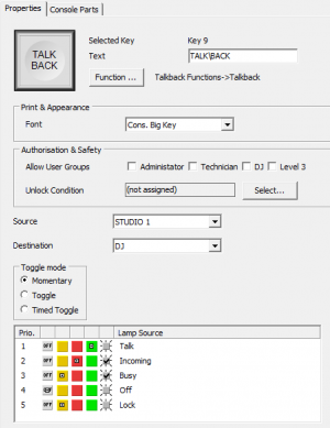
Talkback Functions
| option or subfunction | selection | description |
|---|---|---|
| Talkback | • Establishes a connection between a talk source and a talk destination. • Please see the example in the Virtual Keys section if you want to integrate external talkback panels of other manufactures or custom-made panels. |
|
| Source | • List of all talkback sources configured in the talkback matrix. | |
| Destination | • List of all talkback destinations configured in the talkback matrix. | |
| Momentary | • The function is enabled as long as the key is pressed. | |
| Toggle | • The key is stay-put. | |
| Timed Toggle | • The key is stay-put (short press) or spring-return (long press). | |
| TalkbackReply | • The talkback member that is chosen at Source, calls the talkback member that has talked to this source last. |
|
| Source | • List of all talkback sources configured in the matrix. | |
| Momentary | • The function is enabled as long as the key is pressed. | |
| Toggle | • The key is stay put. | |
| Timed Toggle | • The key is stay put (short press) or spring return (long press). | |
| Talkback List | • Use the encoder to select a talk destination from the talkback members list. This function only shows the List to select the destination and requires a TalkToListMember key. |
|
| Talk Source | • Select a source to talk into. | |
| TalkToListMember | • Select your destination via Talkback List and talk to it with this key. |
|
| Talk Source | • Select a source to talk into. | |
| TalkbackRedirect | • Forward all incoming talks to another destination. | |
| Talk Source | • Select the source of your Talkback Member. | |
| Talk Destination | • Select the destination to forward to. |
Set Mixer Options
Use these key functions to change the behavior of several functions (e.g. PFL) for the current mixer.
| option or subfunction | selection | description |
|---|---|---|
| Direct OffAir | • Will change the conditions when a channel is switched to OffAir Bus. • when deactivated: - OffAir is switched and operated via the 'OffAir' keys. • when activated: - The OffAir state only depends on the Channel's On / Off status. 'OffAir' keys will be locked for operation and only show the current status. - The result on audio busses will be: ⋅ Channel switched OFF + Fader open: signal is present on OffAir audio busses only ⋅ Channel switched ON + Fader open: signal is present on all other audio busses but not on OffAir audio busses |
|
| Set Meter Source | Input | • Switches Channel-PPM sources to “Input”. |
| Pre Fader | • Switches Channel-PPM sources to “Pre Fader”. | |
| After Fader | • Switches Channel-PPM sources to “After Fader”. | |
| PFL1 Mix | • Enables, that several channels can be simultaneously routed on PFL1. | |
| PFL1 Reset | • If the fader of any channel in PFL mode gets opened (it does not matter if the opened channel belongs to PFL bus 1 or 2), all currently active PFL1 routings are reset. | |
| PFL1 Reset Channel | • If a channel is routed on PFL1 and you open its fader, the PFL1 routing of that channel is reset. | |
| PFL1 Return | • If a channel is routed on PFL1 and you open its fader, the PFL1 routing of that channel is reset. If you close the fader, the PFL routing is reactivated. | |
| PFL1 is AFL | • Sets PFL1 to post fader, ignoring the fader state. | |
| AFL1 When Fader On | • Toggles automatically the monitoring mode from PFL to AFL, if the fader of a channel is opened (Faderstart ON). | |
| PFL2 Mix | • Enables, that several channels can be simultaneously routed on PFL1. | |
| PFL2 Reset | • If the fader of any channel in PFL mode gets opened (it does not matter if the opened channel belongs to PFL bus 1 or 2), all currently active PFL1 routings are reset. | |
| PFL2 Reset Channel | • If a channel is routed on PFL1 and you open its fader, the PFL1 routing of that channel is reset. | |
| PFL2 Return | • If a channel is routed on PFL1 and you open its fader, the PFL1 routing of that channel is reset. If you close the fader, the PFL routing is reactivated. | |
| PFL2 is AFL | • Sets PFL2 to post fader, ignoring the fader state. | |
| PFL2 as DJ PFL | • Allows predefined fader position via PFL2 for next Channel Start (alternating to 0) • Requires defined PFL2-Bus • Resets predefined fader position after Fader Start To set DJ Pfl: Press PFL2. Motor fader moves to 0 but is off air. Choose the fader value. Switch PFL2 off. On next fader start, motor fader will move to defined position, alternating from 0 once. |
|
| Channel On Sets Fader 0 dB | • Using Channel ON, Channel OFF (Ext) and Channel ON/OFF (Ext) or external protocol sets the Fader to 0dB. This can also be a mixer option, see Operation Mode - Channel Options |
Profanity Delay
Control keys for the Fixed Processing Profanity Delay. For more information see Fixed Processing/Profanity Delay
| option or subfunction | selection | description |
|---|---|---|
| Start | • Starts filling the memory of the profanity delay. Audio will play slower while filling memory. | |
| Exit | • Stops profanity delay. Audio will play faster to return to real time signal. | |
| Dump | • Clears memory of profanity delay and continues directly with real time signal. Causes signal leap. | |
| Cough | • When you press this button, current program is cut out. Audio will play slower to compensate and fill memory again. |
Tip
Profanity Delay fills faster when detecting silence.
Loudness Metering
| option or subfunction | selection | description |
|---|---|---|
| Start | LDN Meter | Start metering on selected loudness meter. |
| Stop | LDN Meter | Stop metering on selected loudness meter. |
| Reset | LDN Meter | Reset metering on selected loudness meter. |
Note
Loudness value can be displayed on a TFT view. For more Information on Loudness metering, see Level Detects.
Potentiometer
The Potentiometer key function allows to assign a potentiometer to an encoder and control it. When pressing the key again, the encoder is set back to default function.
Potentiometer: ClickSelectto define the potentiometer you want to control.Encoder: ClickSelectto define the encoder which shall control the potentiometer.
Tip
This function is useful to control software potentiometers with an hardware encoder.
DelayNr
The DelayNr key function allows to control a Fixed Processing Delay by an encoder. This function is activated by pressing the defined key. when pressing the key again, the encoder switches back to default function.
Encoder: ClickSelectand assign the encoder you want to use.DelayNr: Select the Fixed Processing that contains the delay. If no fixed processing with a delay is defined, only(None)will be shown.